


USER MANUAL Chapter 7 Application Programming • 147
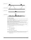
An alternative approach is the dual-loop, where we use two sensors, rotary and linear. The rotary
sensor assures stability (because the position loop is closed before the backlash) whereas the linear
sensor provides accurate load position information. The operation principle is to drive the motor to a
given rotary position near the final point. Once there, the load position is read to find the position error
and the controller commands the motor to move to a new rotary position which eliminates the position
error.
Since the required accuracy is 0.5 micron, the resolution of the linear sensor should preferably be twice
finer. A linear sensor with a resolution of 0.25 micron allows a position error of +/-2 counts.
The dual-loop approach requires the resolution of the rotary sensor to be equal or better than that of the
linear system. Assuming that the pitch of the lead screw is 2.5mm (approximately 10 turns per inch), a
rotary encoder of 2500 lines per turn or 10,000 count per revolution results in a rotary resolution of
0.25 micron. This results in equal resolution on both linear and rotary sensors.
To illustrate the control method, assume that the rotary encoder is used as a feedback for the X-axis,
and that the linear sensor is read and stored in the variable LINPOS. Further assume that at the start,
both the position of X and the value of LINPOS are equal to zero. Now assume that the objective is to
move the linear load to the position of 1000.
The first step is to command the X motor to move to the rotary position of 1000. Once it arrives we
check the position of the load. If, for example, the load position is 980 counts, it implies that a
correction of 20 counts must be made. However, when the X-axis is commanded to be at the position
of 1000, suppose that the actual position is only 995, implying that X has a position error of 5 counts,
which will be eliminated once the motor settles. This implies that the correction needs to be only 15
counts, since 5 counts out of the 20 would be corrected by the X-axis. Accordingly, the motion
correction should be:
Correction = Load Position Error - Rotary Position Error
The correction can be performed a few times until the error drops below +/-2 counts. Often, this is
performed in one correction cycle.
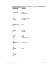
Example motion program:
INSTRUCTION FUNCTION
#A Label
DP0 Define starting positions as zero
LINPOS=0
PR 1000 Required distance
BGX Start motion
#B
AMX Wait for completion
WT 50 Wait 50 msec
LIN POS = _DEX Read linear position
ER=1000-LINPOS-_TEX Find the correction
JP #C,@ABS[ER]<2 Exit if error is small
PR ER Command correction
BGX
JP #B Repeat the process
#C
EN