


Appendices • 194 USER MANUAL
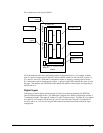
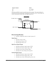
The power outputs must be connected in a driving configuration as shown on the previous page. Here
are the voltage outputs to expect after the Clear Bit and Set Bit commands are given:
Output Command
Result
CB
n
V
pwr
= V
iso
SB
n
V
pwr
= GND
iso
Standard Digital Outputs
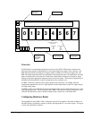
The I/O banks 2-7 can be configured as optically isolated digital outputs, however these banks do not
have the high power capacity as in banks 0-1. In order to configure a bank as outputs, the optical
isolator chips Ux1 and Ux2 are inserted, and the digital input isolator chips Ux3 and Ux4 are removed.
The resistor packs RPx2 and RPx3 are inserted, and the input resistor pack RPx4 is removed.
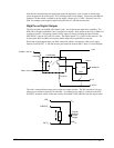
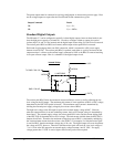
Each bank of eight outputs shares one I/OC connection, which is connected to a DC power supply
between 4 and 28 VDC. The resistor pack RPx3 is optional, used either as a pull up resistor from the
output transistor’s collector to the external supply connected to I/OC or the RPx3 is removed resulting
in an open collector output. Here is a schematic of the digital output circuit:
Internal Pullup
1/4 NEC2505
1/8 RPx3
To DMC-1748 +5V
DMC-1748 I/O
I/O
n
I/OC
n
OUTC
n
1/8 RPx2
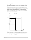
The resistor pack RPx3 limits the amount of current available to source, as well as affecting the low
level voltage at the I/O output. The maximum sink current is 2mA regardless of RPx3 or I/OC voltage,
determined by the NEC2505 optical isolator IC. The maximum source current is determined by
dividing the external power supply voltage by the resistor value of RPx3.
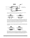
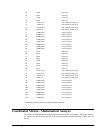
The high level voltage at the I/O output is equal to the external supply voltage at I/OC. However,
when the output transistor is on and conducting current, the low level output voltage is determined by
three factors. The external supply voltage, the resistor pack RPx3 value, and the current sinking limit
of the NEC2505 all determine the low level voltage. The sink current available from the NEC2505 is
between 0 and 2mA. Therefore, the maximum voltage drop across RPx3 is calculated by multiplying
the 2mA maximum current times the resistor value of RPx3. For example, if a 10k ohm resistor pack
is used for RPx3, then the maximum voltage drop is 20 volts. The digital output will never drop below
the voltage at OUTC, however. Therefor a 10k ohm resistor pack will result in a low level voltage of
.7 to 1.0 volts at the I/O output for an external supply voltage between 4 and 21 VDC. If a supply
voltage greater than 21 VDC is used, a higher value resistor pack will be required.