


Chapter 2 Getting Started • 26 USER MANUAL
Step 7b. Connect Sinusoidal Commutation Motors
When using sinusoidal commutation, the parameters for the commutation must be determined
and saved in the controllers non-volatile memory. The servo can then be tuned as
described in Step 8.
Step A. Disable the motor amplifier
Use the command, MO, to disable the motor amplifiers. For example, MOX will turn the
X axis motor off.
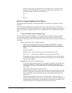
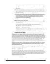
Step B. Connect the motor amplifier to the controller.
The sinusoidal commutation amplifier requires 2 signals, usually denoted as Phase A &
Phase B. These inputs should be connected to the two sinusoidal signals generated by the
controller. The first signal is the axis specified with the command, BA (Step 5). The
second signal is associated with the highest analog command signal available on the
controller - note that this axis was made unavailable for standard servo operation by the
command BA.
When more than one axis is configured for sinusoidal commutation, the controller will
assign the second phase to the command output which has been made available through
the axes reconfiguration. The 2
nd
phase of the highest sinusoidal commutation axis will
be the highest command output and the 2
nd
phase of the lowest sinusoidal commutation
axis will be the lowest command output.
It is not necessary to be concerned with cross-wiring the 1
st
and 2
nd
signals. If this wiring
is incorrect, the setup procedure will alert the user (Step D).
Example: Sinusoidal Commutation Configuration using a
DMC-1348
BAXZ
This command causes the controller to be reconfigured as a DMC-13X8 controller. The
X and Z axes are configured for sinusoidal commutation. The first phase of the X axis
will be the motor command X signal. The second phase of the X axis will be the motor
command the motor command Y signal. The first phase of the Z axis will be the motor
command Z signal. The second phase of the Z axis will be the motor command W signal.
Step C. Specify the Size of the Magnetic Cycle.
Use the command, BM, to specify the size of the brushless motors magnetic cycle in
encoder counts. For example, if the X axis is a linear motor where the magnetic cycle
length is 62 mm, and the encoder resolution is 1 micron, the cycle equals 62,000 counts.
This can be commanded with the command.
BM 62000
On the other hand, if the Z axis is a rotary motor with 4000 counts per revolution and 3
magnetic cycles per revolution (three pole pairs) the command is
BM,, 1333.333
Step D. Test the Polarity of the DACs and Hall Sensor Configuration.
Use the brushless motor setup command, BS, to test the polarity of the output DACs.
This command applies a certain voltage, V, to each phase for some time T, and checks to
see if the motion is in the correct direction.
The user must specify the value for V and T. For example, the command
BSX = 2,700