


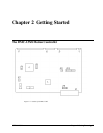

Chapter 2 Getting Started • 20 USER MANUAL
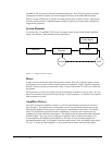
Example: Sinusoidal Commutation Configuration using a DMC-1348
BAXZ
This command causes the controller to be reconfigured as a DMC-1328 controller. The X and Z axes
are configured for sinusoidal commutation. The first phase of the X axis will be the motor command
X signal. The second phase of the X axis will be Y signal. The first phase of the Z axis will be the
motor command Z signal. The second phase of the Z axis will be the motor command W signal.
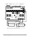
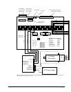
Step 6. Make Connections to Amplifier and Encoder.
Once you have established communications between the software and the DMC-13X8, you are ready
to connect the rest of the motion control system. The motion control system typically consists of an
ICM-1900 Interface Module, an amplifier for each axis of motion, and a motor to transform the current
from the amplifier into torque for motion. Galil also offers the AMP-19X0 series Interface Modules
which are ICM-1900’s equipped with servo amplifiers for brush type DC motors.
If you are using an ICM-1900, connect the 100-pin high-density cable to the DMC-13X8 and to the
connector located on the AMP-19x0 or ICM-1900 board. The ICM-1900 provides screw terminals for
access to the connections described in the following discussion.
System connection procedures will depend on system components and motor types. Any combination
of motor types can be used with the DMC-13X8. If sinusoidal commutation is to be used, special
attention must be paid to the reconfiguration of axes.
Here are the first steps for connecting a motion control system:
Step A. Connect the motor to the amplifier with no connection to the controller. Consult the
amplifier documentation for instructions regarding proper connections. Connect and
turn-on the amplifier power supply. If the amplifiers are operating properly, the motor
should stand still even when the amplifiers are powered up.
Step B. Connect the amplifier enable signal.
Before making any connections from the amplifier to the controller, you need to verify
that the ground level of the amplifier is either floating or at the same potential as earth.
WARNING: When the amplifier ground is not isolated from the power line or when it has a different potential
than that of the computer ground, serious damage may result to the computer controller and amplifier.
If you are not sure about the potential of the ground levels, connect the two ground
signals (amplifier ground and earth) by a 10 KΩ resistor and measure the voltage across
the resistor. Only if the voltage is zero, connect the two ground signals directly.
The amplifier enable signal is used by the controller to disable the motor. This signal is
labeled AMPENX for the X axis on the ICM-1900 and should be connected to the enable
signal on the amplifier. Note that many amplifiers designate this signal as the INHIBIT
signal. Use the command, MO, to disable the motor amplifiers - check to insure that the
motor amplifiers have been disabled (often this is indicated by an LED on the amplifier).
This signal changes under the following conditions: the watchdog timer activates, the
motor-off command, MO, is given, or the OE1 command (Enable Off-On-Error) is given
and the position error exceeds the error limit. As shown in Figure 3-3, AEN can be used
to disable the amplifier for these conditions.
The standard configuration of the AEN signal is TTL active high. In other words, the
AEN signal will be high when the controller expects the amplifier to be enabled. The
polarity and the amplitude can be changed if you are using the ICM-1900 interface board.
To change the polarity from active high (5 volts = enable, zero volts = disable) to active
low (zero volts = enable, 5 volts = disable), replace the 7407 IC with a 7406. Note that
many amplifiers designate the enable input as ‘inhibit’.