


10
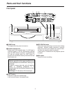
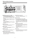
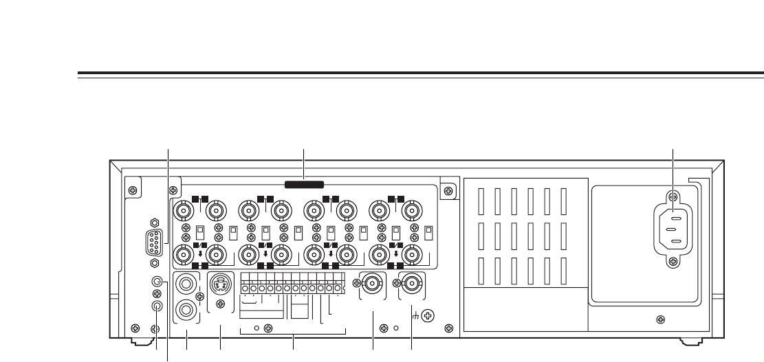
Parts and their functions
1
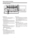
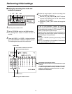
CAMERA IN connectors
1
to
qV
(BNC),
75Ω termination/loop through selector switches
1
to
8
, 75Ω termination switches
9
to
qV
The camera and other external video input signals
(max. 16 inputs) are connected to these
connectors.
To use these connectors, select REC TYPE as the
RECORDING T-MODE & CAMERA setting on
menu screen P3.
<Note>
The 75Ω termination/loop through selector switches
1
to
8
have 3 positions.
Switches
9
to
qV
have 2 positions, 75 Ω termination
ON and OFF.
2
RS-232C connector
This is used to connect a personal computer or
other such device for controlling the unit.
3
MIC IN jack (M3)
This is used to connect the audio input signals from
the microphone. (600Ω impedance)
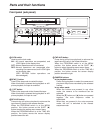
4
REMOTE connector
This is used to connect the model AG-A11 remote
controller available as an optional accessory.
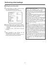
5
AUDIO connectors (pin jacks)
These are the audio input and output connectors.
When a microphone has been connected to the
MIC IN jack, the sound from this jack takes
precedence in recording.
6
S-VIDEO OUT connector (4P)
This is used to connect the unit to a device
equipped with an S-video input connector.
7
Terminal section
8
EXT SW IN/VIDEO OUT connector (BNC)
The same video signals are output as the signals
from the VIDEO OUT connector
9
. When EXT SW
IN is selected as the EXT SWITCHER MODE
setting on menu screen P7, the connector can be
made to serve as an input connector of the external
switcher.
9
VIDEO OUT connector (BNC)
The video signals from the camera switched by the
internal sequential switcher are output from this
connector during recording.
During playback, the playback pictures of the
recorded tape are output.
The menu screen or time adjustment screen is also
displayed.
:
AC IN socket
One end of the accessory power cord is connected
to this socket, and the other end is connected to a
household AC 120V power outlet.
~AC IN
75
™
ON ON ON ON ON ON ON ON
75
™
CAMERA IN
75
™
75
™
OFF OFF OFF OFF
75
™
OFF
75
™
OFF
75
™
OFF
75
™
OFF
AUDIO
S-VIDEO
OUT
IN
OUT
1
2 GND
IN
REC IN GND
GND
TIME ADJ IN
TAPE END OUT
RESET
ALARM
EXT
TIMER
OUT
IN
OUT
WARNING
/REC OUT
EXT SW IN
/VIDEO OUT
VID
EO OU
T
RS-
232C
MIC IN
REMOTE
34
12 34 56
78
78
9
10
11
12 13 14 15 16
12 56
1 :
5 6 8 97
3
4
2
Rear panel