53
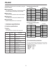
1. Hardware specifications
(1) Interface specifications
Connector:
D-Sub 9-pin
DCE specifications (straight cable supported)
Pin No. Signal Description
1 GND GND
2 SD (TXD) Transmitted Data
3 RD (RXD) Received Data
4 ER (DTR) Data Terminal Ready
5 SG Signal GND
6 DR (DSR) Data Set Ready
7 CS (CTS) Clear to Send
8 RS (RTS) Request to Send
9 N.C
=====
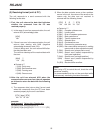
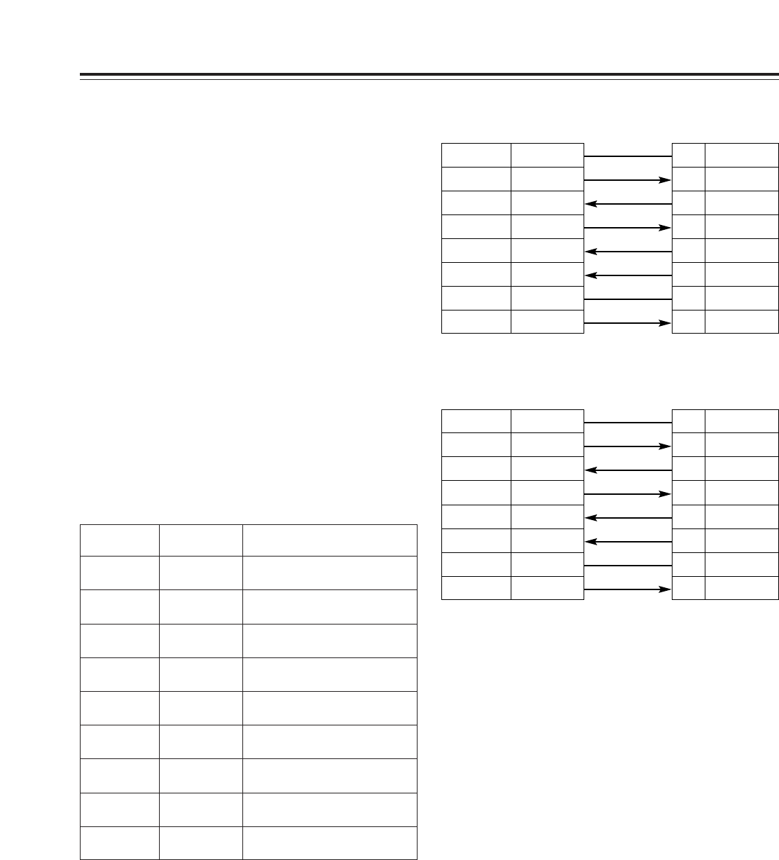
Example of connections (9P)
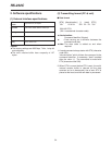
(2) Communication parameters
The unit’s communication parameters are as follows.
To change any of these parameters, make the
changes on the menus.
Baud rate : 9600 bps
Bit length : 7 bits
Stop bit : 1 bit
Parity : Odd
1CD
3SD
2
RD
7RS
8CS
6
DR
5SG
4ER
PC side
1 GND
3
RD (RXD)
2 SD (TXD)
7 CS (CTS)
8 RS (RTS)
6 ER (DTR)
5SG
4
DR (DSR)
Unit side
RS-232C
The following functions can be controlled by using the
RS-232C interface.
$
Basic operations
The same basic operations as those performed by
the unit’s buttons and switches can be initiated.
$
Status checks
The unit’s current operation mode can be checked.
$
Setting menus
The setting menu items can be detected and set.
$
Search function
Specific frame positions can be searched.
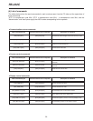
Example of connections (25P)
1FG
2SD
3
RD
4RS
5CS
6
DR
7SG
20 ER
PC side
1 GND
3
RD (RXD)
2 SD (TXD)
7 CS (CTS)
8 RS (RTS)
6 ER (DTR)
5SG
4
DR (DSR)
Unit side


