


18
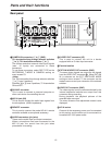
Connections
~AC IN
75
™
ON ON ON ON ON ON ON ON
75
™
CAMERA IN
75
™
75
™
OFF OFF OFF OFF
75
™
OFF
75
™
OFF
75
™
OFF
75
™
OFF
AUDIO
S-VIDEO
OUT
IN
OUT
1
2 GND
IN
REC IN GND
GND
TIME ADJ IN
TAPE END OUT
RESET
ALARM
EXT
TIMER
OUT
IN
OUT
WARNING
/REC OUT
EXT SW IN
/VIDEO OUT
VID
EO OU
T
RS-
232C
MIC IN
REMOTE
34
12 34 56
78
78
9
10
11
12 13 14 15 16
12 56
No. 1 No. 16
3
2
1
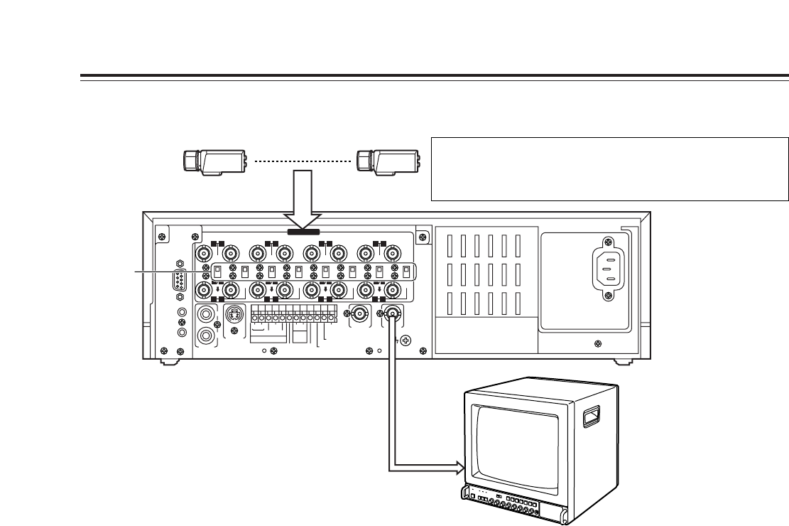
1
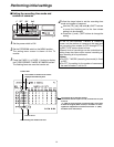
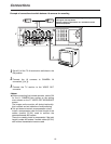
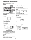
Set all 8 of the 75 Ω termination switches to the
ON position.
2
Connect the 16 cameras to CAMERA IN
connectors
1
to
qV
.
3
Connect the TV monitor to the VIDEO OUT
connector.
Example of connections to switch between 16 cameras for recording
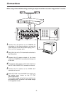
<Notes>
O
When connecting line-locked cameras, select ON
for the LL CAMERA item setting on the setting
menu shown on the P7 VIDEO OUT SEQUENCE
screen.
The images on the monitor will shake fractionally:
this is normal and not indicative of malfunctioning.
O
This unit does not contain a compensation circuit.
Install a compensator when the total length of the
cables (coaxial 3C-2V) used to connect the
cameras exceeds 200 meters.
There is no need to install a compensator if the total
length is under 400 meters if coaxial cables (5C-2V)
with minimal transmission loss are used.
This unit does not have an AGC (auto gain control) function for
video signal level adjustment.
Therefore, take due care with the 75 Ω termination for the
peripheral equipment.