


38
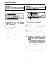
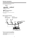
External interface preparation
specifications
O
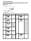
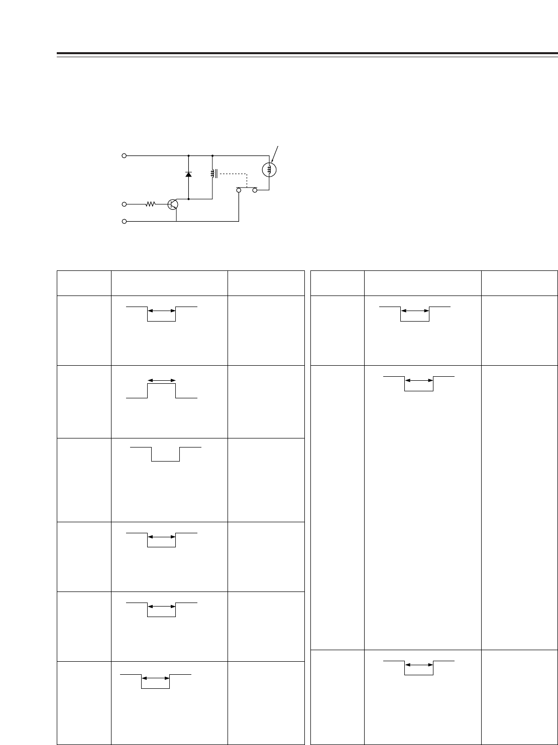
Use devices with ratings which support the actual
operating conditions.
Example of lamp lighted by HIGH signal
(Lamp, etc.)
Power
Relay
Control signal
GND
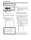
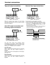
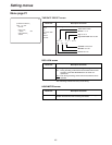
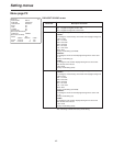
Terminal signal levels
Terminal RemarksSignal level
ALARM IN
1/2
Ground input
V IH = 4.0 V to 5.0 V
V IL = 0.0 V to 0.6 V
T
S
100 ms
ALARM
RESET IN
High input
V IH = 4.0 V to 5.0 V
V IL = 0.0 V to 0.6 V
T
S
100 ms
T
V IH
V IL
T
V IH
V IL
REC IN Ground input
V IH = 4.0 V to 5.0 V
V IL = 0.0 V to 0.6 V
T
S
100 ms
T
V IH
V IL
EXT TIMER
IN
Ground input
Recording is
performed during
the V IL input (T).
V IH = 4.0 V to 5.0 V
V IL = 0.0 V to 0.6 V
T: Recording time
T
V IH
V IL
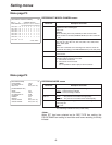
EXT TIMER
OUT
Ground output
Output time T is set
using the EXT
TIMER OUT item on
the menu screen
shown on P7
TERMINAL
OUTPUT SELECT.
V OL = 0.0 V to 0.6 V
V OL
T
OPEN OPEN
ALARM OUT Ground output
The output format is
set using the
ALARM/SENSOR
OUT item on the
menu screen shown
on P7 TERMINAL
OUTPUT SELECT.
V OH = 11.0 V to 13.0 V
V OL = 0.0 V to 0.6 V
4.7 kΩ pull-up resistor (+12V) output
V OH
V OL
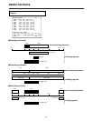
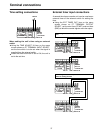
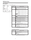
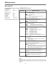
Terminal RemarksSignal level
TIME ADJ IN Ground input
V IH = 4.0 V to 5.0 V
V IL = 0.0 V to 0.6 V
T
S
100 ms
T
V IH
V IL
TAPE END
OUT
Ground output
When REPEAT has
been selected as
the (TAPE END)
MODE setting on
the menu screen
shown on P5 (VTR
MODE SELECT),
output time T is 2
seconds. If a setting
other than REPEAT
is selected, the
signal will continue
to be output until
one of the function
buttons is pressed.
The signal will
continue to be
output until one of
the function buttons
is pressed also
when a setting other
than OFF has been
selected as the
LEVEL setting on
the menu screen
shown on P6 TAPE
REMAIN.
V OH = 11.0 V to 13.0 V
V OL = 0.0 V to 0.6 V
4.7 kΩ pull-up resistor (+12V) output
T
V OH
V OL
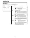
WARNING/R
EC OUT
Ground output
Open drain output
V OL = 0.0 V to 1.0 V
Max. 200 mA drive enabled
T
V OH
V OL