


19
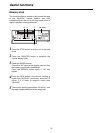
Connections
~AC IN
75
™
ON ON ON ON ON ON ON ON
75
™
CAMERA IN
75
™
75
™
OFF OFF OFF OFF
75
™
OFF
75
™
OFF
75
™
OFF
75
™
OFF
AUDIO
S-VIDEO
OUT
IN
OUT
1
2 GND
IN
REC IN GND
GND
TIME ADJ IN
TAPE END OUT
RESET
ALARM
EXT
TIMER
OUT
IN
OUT
WARNING
/REC OUT
EXT SW IN
/VIDEO OUT
VID
EO OU
T
RS-
232C
MIC IN
REMOTE
34
12 34 56
78
78
9
10
11
12 13 14 15 16
12 56
5
34
1
2
No. 1 No. 16
2
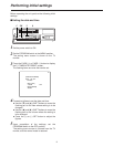
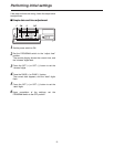
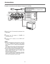
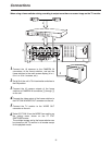
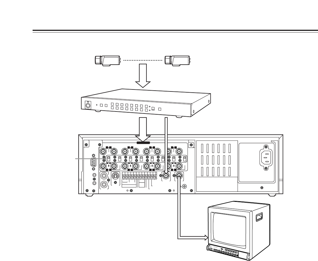
Set all 8 of the unit’s 75 Ω termination switches to
the ON position.
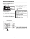
1
Connect the 16 cameras to the CAMERA IN
connectors of the frame switcher, and set the
frame switcher to the multi-screen display (4-in-1,
9-in-1 or 16-in-1 screens, etc.).
3
Connect the 16 camera outputs of the frame
switcher to CAMERA IN connectors
1
through
qV
on the unit.
4
Connect the video output of the frame switcher to
the EXT SW IN/VIDEO OUT connector on the unit.
5
Connect the TV monitor to the VIDEO OUT
connector on the unit.
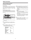
6
Select EXT SW IN as the MODE item setting on
the setting menu shown on the P7 EXT
SWITCHER screen.
The multiple images set by the frame switcher can
be viewed on the TV monitor in all modes except
for the playback mode.
When using a frame switcher during recording to output more than one screen image on the TV monitor