


11
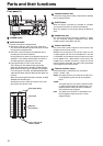
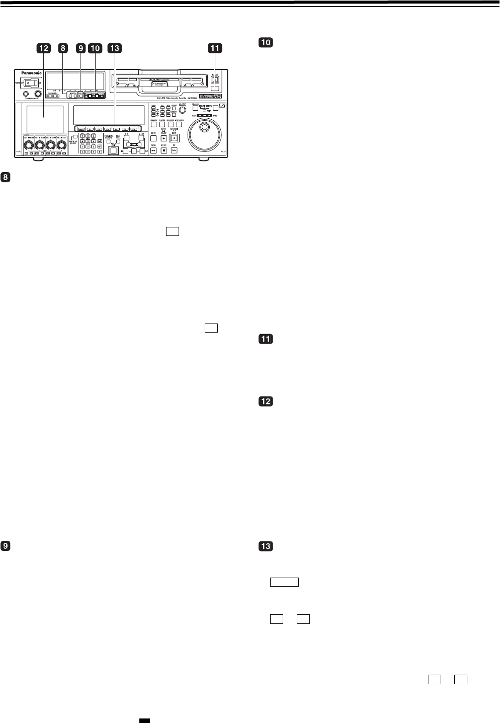
Parts and their functions (continued)
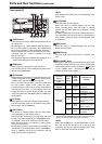
Front panel (2)
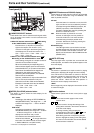
MONITOR SELECT buttons
These buttons are used to select the audio signals which
are to be output to the monitor L and R connectors and
headphones jack.
z
When OFF has been selected as the M MIX setting
on the <AUDIO SHIFT2> menu (factory setting):
Each time the L (or R) button is pressed, the
signal to be output to the monitor L (or R)
connector is changed in the following sequence
and displayed on the audio level meter: CH1 >
CH2 > CH3> CH4 > CH5 > CH6 > CH7 >
CH8 > CUE > CH1, etc.
z When L, R or L/R has been selected as the M
MIX setting on the <AUDIO SHIFT2> menu:
At this setting, the signals of a multiple number of
channels can be mixed and output.
When the number key corresponding to the
channel whose signals are to be monitored is
pressed while the L (or R) button is held down,
that channel is selected and its signals are
displayed on the audio level meter. By
performing the same operation, the selected
channel can be de-selected.
However, a maximum of only two channels from
CH1 to CH4 and a maximum of only two
channels from CH5 to CH8 can be selected.
Example of channels which can be selected:
CH1 i CH3 i CH5 iCH8 > OK
CH1 + CH2 + CH4 > NG
METER (FULL/FINE) selector button
This button is used to select the scale display for the
audio level meter.
FULL mode:
According to the settings in SETUP MENU No.
763 (METER SCALE)*, the range from
j∞ dB
to 0 dB or the range from
j∞ dB to +20 dB is
displayed.
FINE mode:
According to the settings in SETUP MENU No.
763 (METER SCALE)*, the range from j24 dB to
j15 dB or the range from j4 dB to +5 is
displayed at intervals of every 0.5 dB.
The reference level is displayed with the
reference level indicator on the right side of the
level meter. The reference level can be changed
in SETUP MENU No. 776 (REF LEVEL)
* This menu is not displayed for AJ-HD1800E.
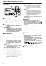
REMOTE buttons and RS-232C display
These buttons are used when this VTR is to be controlled
from an external component using the REMOTE, RS-
232C or parallel connector.
9P 1394:
Press the button for 2 seconds or more, the LED
lights, and the unit can be controlled by a device
connected through the REMOTE connector, the
(IN/O
UT) connector, or the DVCPRO/DV
connector. Release the control by pressing the
button for 2 seconds or more.
50P: When this button is pressed for 2 or more
seconds, its LED lights, and it is possible to
control the VTR from a unit which has been
connected using the 50-pin parallel mode
connector. Release the control by pressing the
button for 2 seconds or more.
RS-232C display:
This LED lights when communication has been
enabled between the VTR and the unit which has
been connected to the RS-232C connector. The
display can be switched in SETUP MENU No.204
(RS232C SEL).
AUTO OFF lamp
This lamp lights when a problem has occurred with the
VTR’s operation, and details of the problem appear on the
time code display.
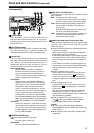
LCD monitor
The monitor is operated as a simple monitor for playing
back tapes or displaying EE images and menu display.
If the VTR is left in a state where no controls on the front
panel are operated or where the tape is not running, the
monitor display is automatically turned off in order to
protect the monitor. When the next VTR operation is
started, the monitor display comes back on.
<Note>
Some images may not be displayed. Use another monitor
to check the images.
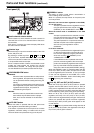
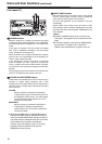
Function buttons
These buttons operate the function menu (refer to page
38).
:
This is used to switch pages on the current
function menu.
to :
These are used to change the settings of the
setting items enclosed in the frame at the bottom
of the time code display.
To change a setting, keep pressing the
corresponding function button ( to ) until
the desired numerical value appears;
alternatively, press the corresponding function
button to highlight the setting of the setting item,
and then turn the ADJUST dial until the desired
numerical value is obtained.
F6
F6
SHIFT
F1 F6
F1 F6