


96
Setup menus (continued)
<VIDEO>
The underlining (__) denotes the factory setting mode.
*1 When the 23/24 Hz mode, 25 Hz (HD, SD) mode, or 50 Hz
(HD, SD) mode is selected in System Menu No. 25 (SYSTEM
FREQ), this item is not displayed.
*2 When the 23/24 Hz mode, 25 Hz (HD) mode, or 50 Hz (HD)
mode is selected in System Menu No. 25 (SYSTEM FREQ),
this item is not displayed.
*3 When the 25 Hz (HD, SD) mode or 50 Hz (HD, SD) mode is
selected in System Menu No. 25 (SYSTEM FREQ), this item is
not displayed.
*4 This item is displayed only when the 25 Hz (SD) mode is
selected in System Menu No. 25 (SYSTEM FREQ)
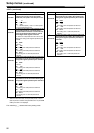
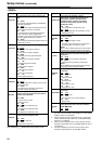
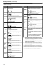
No./Item Description of setting
600*
1
VIDEO IN SEL
For selecting the video signal which is to be
input.
0000 INT SG
The internal signal selected by the VIDEO INT
SG item is generated.
0001 HDSDI
The serial video signal which has been input to
the HD SDI IN connector is selected.
0003 1394
For selecting the compressed digital signals
input to the DV connector (digital video
interface). In this case, the audio input signals
are also signals from the DV connector.
0004 SD SDI
For selecting the serial image signals input to the
SD SDI IN connector
601*
1
VIDEO INT SG
For selecting the type of internal signal.
0000 100%CB
A 100% color bar signal is selected.
0001 75%CB
A 75% color bar signal is selected.
0002 SMPTE
An SMPTE color bar signal is selected.
0003 ARIB
An ARIB color bar signal is selected.
0004 MB
A multiburst signal is selected.
0005 RAMP
A ramp signal is selected.
0006 BLACK
A black signal is selected.
0007 PLL
A PLL signal is selected.
0008 EQ
An EQ signal is selected.
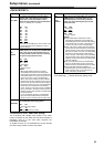
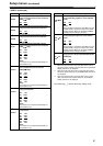
602*
1
SDI IN MODE
For selecting how to process the serial input.
0000 DR OFF
The 8 higher bits after rounding up the 2 lowest
bits are recorded.
0001 DR ON
The signal with 8 higher bits, obtained by
dynamic rounding, is recorded.
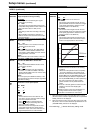
603
V-MUTE SEL
For selecting whether the image input signal is
muted or not when blank parts of the tape are
detected during playback
0000 N MUTE
The signals are not muted.
(They are frozen.)
0001 GRAY
The signals are muted with gray.
0002 BLACK
The signals are muted with black.
0003 NOISE
The signals are muted with noise.
604*
1
FREEZE SEL
For selecting the freeze mode of the still
pictures and slow playback mode.
0000 FIELD
Field freeze, field slow
0001 FRAME
Frame freeze, frame slow
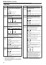
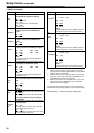
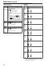
No./Item Description of setting
605*
1
INTERPOLATE
During field slow playback, vertical
interpolation is conducted automatically to
minimize the up/down movement of the
playback pictures. However, this setting
enables the interpolation operation to be
forcibly set to OFF.
0000 OFF
The interpolation is forcibly set to OFF
0001 AUTO
During slow playback, the interpolation is auto-
matically set to ON
606
SD MONI O
SEL
For switching the MONITOR output signal from
SD SDI connector.
0000 MONI
The MONITOR signal is output.
0001 SDI
The same video signal as the one output from
the SD SDI OUT1 connector is output.
<Note>
When 1 (SDI) is selected, the time code and other
information are not superimposed on the display.
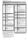
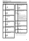
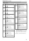
619*
4
V_FILTER
This is used to select the method to process the
images using the vertical filter during down-
conversion.
0000 FIELD
The images are processed by field basis.
0001 FRAME
The images are processed by frame basis.
<Note>
When “FRAME” has been selected, the resolution
is improved, but the images may flicker.
620*
2
DOWNCON
MODE
For selecting the picture frame during down-
conversion.
0000 FIT-V
Side cut mode
0001 FIT-H
Letter box mode
0002 FIT-HV
Squeeze mode
0003 14:9
Semi letter box 14:9
0004 13:9
Semi letter box 13:9
621*
3
UPCON MODE
For selecting the picture frame during up-
conversion.
0000 FIT-V
Side panel mode
0001 FIT-H
Top and bottom cut in vertical direction
0002
FIT-HV
Stretch mode
622
D/C RESP
H
For selecting the horizontal frequency band
during down-conversion and line conversion
(1080i <> 720p).
0000 WIDE
0001 STD