


138
Connector signals (continued)
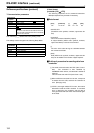
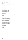
PARALLEL REMOTE (50P)
Refer to 50P IN/OUT ASSIGN on the function menu (page
74) for the connection pin signals.
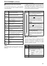
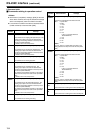
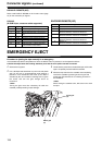
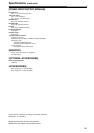
EMERGENCY EJECT
Procedure to ejecting the tape manually in an emergency
If the cassette tape fails to be ejected even when the EJECT button is pressed, it can be ejected as follows.
z Follow the steps below after making absolutely sure that the unit’s power has been turned off.
1 Remove the top panel.
2 Use a Phillips-head screwdriver to push in the red plastic
gear (A) and turn it counterclockwise while keeping it
pushed in. The mechanism that winds up the tape is
activated by this, and it makes a latching sound. Ignore
the sound, and turn the gear through about 10
revolutions.
<Note>
Turning the gear more than necessary will strain the
cassette, possibly resulting in tape damage.
3 Check that the posts have unloaded the tape and that the
tape is completely housed inside the cassette.
4 When the tape returns to the cassette case completely,
remove the cassette by pressing and turning the red
plastic gear (B) clockwise for front loading as shown in
the illustration.
<Note>
When closing the cassette cover, take care not to catch
the tape.
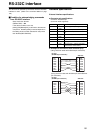
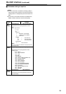
RS-232C
(D-SUB 25-pin, crossover cable supported)
Pin No. Signal Description
1 FG Protective ground (frame ground)
2 RXD Received data (data is sent to PC)
3 TXD Transmitted data (data is received from
PC)
4 CTS Clear to send (shorted with pin 5)
5 RTS Request to send (shorted with pin 4)
6 DTR Data terminal ready (no processing)
7 SG Signal ground
20 DSR Data set ready (+ voltage output after
communication enable status)
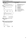
ENCODER REMOTE(15P)
Pin No. Signal
1 FRAME GROUND
4REM (G)
7REM RX (X)
REMOTE CONTROL PROTOCOL RECEIVE
8REM TX (X)
REMOTE CONTROL PROTOCOL TRANSMIT
14 REM RX (Y)
REMOTE CONTROL PROTOCOL RECEIVE
15 REM TX (Y)
REMOTE CONTROL PROTOCOL TRANSMIT
Plastic gear
(A)
Plastic gear
(B)