


19
Parts and their functions (continued)
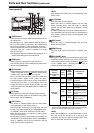
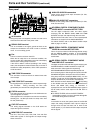
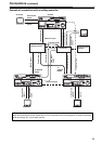
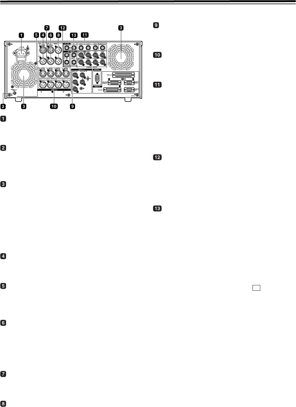
Rear panel
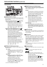
AC IN socket
Using the power cord supplied, connect one end to this
socket and the other end to the power outlet.
SIGNAL GND terminal
This is connected to the signal ground terminal on the
component connected to this VTR in order to minimize
noise. It is not a safety ground.
Fan
The fan is used to cool down the VTR.
When the fan stops due to an abnormal condition, the
warning symbol (W) is displayed on the time code display
section and a warning beep is sounded.
If the VTR is made to continue operating in the warning
status, the temperature inside the deck rises, and when it
exceeds the safety temperature, all the VTR’s operations
will be shut down.
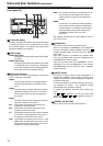
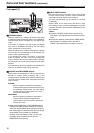
TIME CODE IN connector
This connector is used to record an external time code
onto the tape.
TIME CODE OUT connector
During playback, the playback time code is output through
this connector. During recording, the time code
generated by the internal time code generator is output.
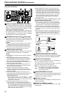
CUE IN connector
The analog signals to be recorded on the CUE tracks are
input through this connector.
Audio signals from a microphone can also be recorded by
selecting the j60 dB input mode for setup menu item
No.704 (CUE IN LV).
CUE OUT connector
The analog signals recorded on the CUE tracks are
output through this connector.
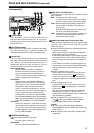
MONITOR OUT connectors
The CH1, CH2, CH3, CH4, CH5, CH6, CH7 and CH8
PCM audio signals or CUE signals are output through
these connectors.
ANALOG AUDIO IN connectors
These are the analog audio input connectors (for CH1,
CH2, CH3 and CH4).
ANALOG AUDIO OUT connectors
These are the analog audio output connectors (for CH1,
CH2, CH3 and CH4).
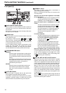
HD SERIAL DIGITAL COMPONENT AUDIO
VIDEO IN/OUT connector/ACTIVE THRU
The HD digital component audio and video signals
complying with the SMPTE 292M, 296M and 299M
standards are input and output through this connector.
Signals with the time code, menu or other superimposed
information are output from the HD SDI MONITOR.
For INPUT CHECK, refer to the INPUT CHECK output
table on pages 17 and 18.
SD SERIAL DIGITAL COMPONENT AUDIO
VIDEO IN connector/ACTIVE THRU
This is an input connector for SD SDI signals that comply
with the SMPTE 259M-C, 272M-A, or ITU-R BT.656-4
standards. The SD SDI input acts as an up converter and
records data.
SD SERIAL DIGITAL COMPONENT AUDIO
and VIDEO OUT connectors
The digital component audio and video signals complying with
the SMPTE 259M-C or 272M-A standard are output from
these connectors. Video signals are output during
DVCPRO50M/25M/DV/DVCAM compatible playback and
down-converting output. Video images are output from the SD
SDI MONITOR together with supers such as the TC/Menu.
Using setup menu item No.606 (SD MONI O SEL), it is also
possible to make the SD SDI MONITOR output the same
output as SD SDI OUT1 (no information superimposed).
When “SD SDI” has been selected as the (VID IN) setting
on the <VIDEO> menu and “THRU” has been selected as the
No.107 (EE MODE SEL) setting, no information is
superimposed onto the SD SDI MONITOR output signals in
the EE mode, and the same output as SD SDI OUT1 is
delivered.
z For INPUT CHECK, refer to the INPUT CHECK
output table
on pages 17 and 18. Note that the signals
are muted during cross conversion.
<Note>
In the 23/24 Hz mode, the system phase of the SD SDI
output and analog composite video output is subject to
change when the tape has been set to travel at the
normal speed (1k) so that the HD SDI output and phase
will be aligned.
F1