


10
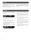
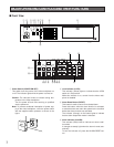
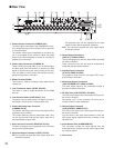
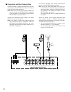
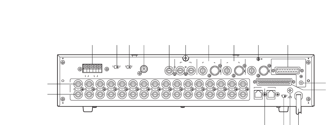
$1 Camera Output Connectors (CAMERA OUT)
The video signal connected to the CAMERA IN connec-
tor is looped through to this connector with an automat-
ic 75 Ω termination.
The camera control signal multiplexed on the video sig-
nal is not available at this connector. When the power
switch of the video multiplexer is turned off, no signal is
present at this connector.
$22 Camera Input Connectors (CAMERA IN)
These connectors accept either a color or B/W compos-
ite video signal from the cameras. In addition, the VD2
signal for synchronizing the vertical timing of the cam-
eras, and data to control camera site devices are multi-
plexed through these connectors.
$3 RS485 Terminal (RS485)
This terminal is used to exchange control data with the
camera site.
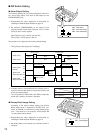
$4 Line Termination Switch (TERM., OFF/ON)
This switch is used to enable termination of the RS485
terminal.
$5 Line Selection Switch (LINE SELECT, 2/4)
This switch lets you select either Full Duplex (4 lines) or
Half Duplex (2 lines) for the communication lines.
$6 Camera Switching Input Connector
(CAMERA SW IN)
The camera switching pulse from the time lapse VCR is
supplied to this connector.
The camera switching interval (Sequential Dwell Time)
can be synchronized with the time lapse mode set in
the associated time lapse VCR.
$7 Gen-Lock Input Connector (GENLOCK IN (VS))
The Gen-Lock signal can be supplied to this connector
for synchronizing the system.
$8 Spot Input/Output Connectors (SPOT, OUT/IN)
IN: This connector accepts the video output signal from
the external system.
The supplied video can be displayed on the spot
monitor screen with the specified conditions.
OUT: This connector supplies the video output signal
for the spot monitor.
$9 Record Output Connectors
(REC OUT, VIDEO/S-VIDEO)
The recording signal for the time lapse VCR is provided
via these connectors.
These connectors can also be used as multiscreen 2
output with the specified conditions.
%0 Playback Input Connectors
(PLAY IN, VIDEO/S-VIDEO)
The playback signal from the time lapse VCR is sup-
plied to these connectors.
%1 Multiscreen Output Connectors
( MULTISCREEN OUT, VIDEO/S-VIDEO)
The video output signal for the multiscreen monitor is
provided via these connectors
%2 RS-232C Port (VCR CONTROL, RS-232C)
The VCR control signal for the time lapse VCR is provid-
ed via this connector.
Connecting a PC to this connector will allow you to
remote control the video multiplexer.
%3 Remote Output Connector
(VCR CONTROL, REMOTE OUT)
The VCR control signal for the time lapse VCR is provid-
ed via this connector.
You can select in the setup menu whether to have the
VCR control signal supplied from this connector or the
RS-232C Port.
%4 Alarm/Remote Port (ALARM/REMOTE)
This connector accepts the alarm signals from the
associated alarm contacts and the control signals from
the external system.
%5 Power Cord
■ Rear View
16 15 14 13 12 11
11
10987654321
16 15 14
13 12
1098765
43
21
A B
T
A B
R
G
N
D
G
N
D
RS485 TERM.
LINE
SELECT
CAMERA
SW IN
GENLOCK
IN (VS)
OFF ON 2 4
SPOT
REC OUT
PLAY IN
MULTISCREEN OUT
VCR CONTROL
RS–232C
OUT I N
VIDEO S–VIDEO S–VIDEO
S–VIDEOVIDEO
VIDEO
REMOTE
ALARM/REMOTE
OUT
TERM.
OFF
INOUT
ON
SIGNAL
GND
DATA
CAMERA
IN
CAMERA
OUT
$1
$2
$3 $4 $5 $6 $7 $8 $9 %0 %1 %2
%3
%4
%5%6%7%8