


20
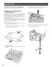
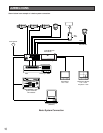
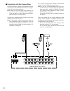
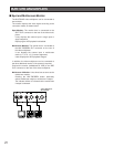
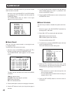
■ Connection with Alarm Sensors
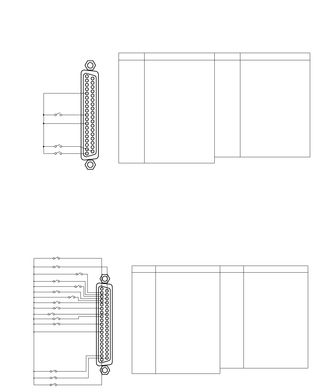
Connect the sensor switches to the ALARM/REMOTE port on the rear of the video multiplexer as shown in the example
below.
Notes:
• Alarm inputs simultaneously or at very short intervals will be ignored. Allow for an interval of at least 100 ms from one
alarm input to the next.
• Connect Pin#5, Alarm/Remote Select Input to Pin#12, GND.
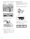
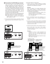
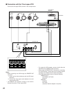
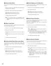
■ Connection with External Remote Control Switches
Connect the switches (dry contact or open collector input) to the ALARM/REMOTE port on the rear of the video multiplexer
as shown in the example below.
Notes:
• Pin#6, Sequence SW for Spot Output and the Pin#8, Alarm Recover Input can also accept DC voltages of 5 V (high
level) and 0 V (low level) besides the switch contact signals.
The multiplexer recognizes falling edge (high to low transition) as an input.
• Pin#5, Alarm/Remote Select Input must be open.
37
19
20
1
SW2
SW1
SW16
GND
ALARM/REMOTE
1
2
3
4
5
6
7
8
9
10
11
12
13
14
15
16
17
18
19
Function
Electronic Zoom
Sequence
Spot
Alarm/Remote Select Input
Sequence SW for Spot Output
Not Used
Alarm Recover Input
Alarm Output
Alarm 16
Alarm 14
Ground
Alarm 11
Alarm 9
Alarm 8
Alarm 6
Ground
Alarm 3
Alarm 1
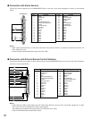
Pin No. Designation
20
21
22
23
24
25
26
27
28
29
30
31
32
33
34
35
36
37
Still Picture
VCR/Camera Select
Multiscreen Select
Multiscreen
Ground
Alarm & SW Output
Time Adjust Input
Alarm Reset Output
Ground
Alarm 15
Alarm 13
Alarm 12
Alarm 10
Ground
Alarm 7
Alarm 5
Alarm 4
Alarm 2
Pin No. Designation
37
19
20
1
1
2
3
4
5
6
7
8
9
10
11
12
13
14
15
16
17
18
19
Function
Electronic Zoom
Sequence
Spot
Alarm/Remote Select Input
Sequence SW for Spot Output
Not Used
Alarm Recover Input
Alarm Output
Camera 16
Camera 14
Ground
Camera 11
Camera 9
Camera 8
Camera 6
Ground
Camera 3
Camera 1
Pin No. Designation
20
21
22
23
24
25
26
27
28
29
30
31
32
33
34
35
36
37
Still Picture
VCR/Camera Select
Multiscreen Select
Multiscreen
Ground
Alarm & SW Output
Time Adjust / Sequence SW
Alarm Reset Output
Ground
Camera 15
Camera 13
Camera 12
Camera 10
Ground
Camera 7
Camera 5
Camera 4
Camera 2
Pin No. Designation
SW1
SW2
SW3
SW16
•
•
•
•
•