


14
C If another alarm is received before the existing alarm is
reset, the alarm output lasts as long as the duration set
for the succeeding alarm.
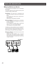
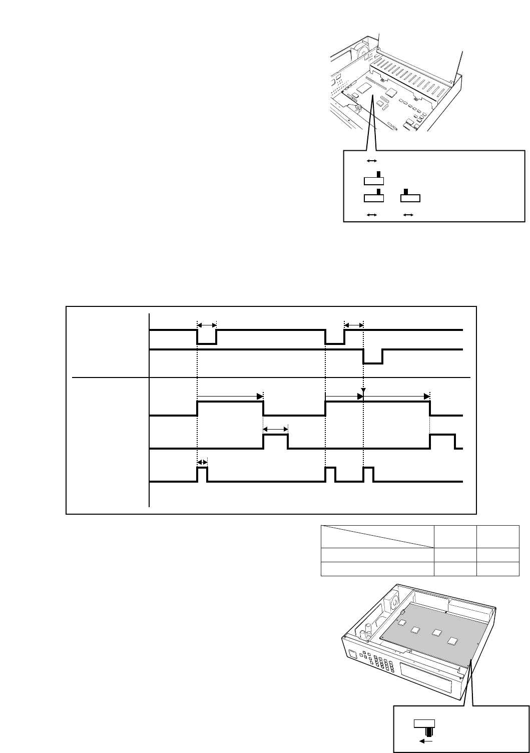
• The O.C position of SW3, SW4, and SW5 corresponds
to their 0/5 V position as shown in the table.
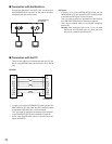
● Dummy Black Image Setting
According to the factory default setting, the Dummy
Black Image signal is supplied to the REC OUT con-
nector as needed to overwrite any image displayed by
error. If this function is not required, set the switch SW
1 to the position shown below.
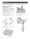
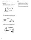
1. Disassemble the video multiplexer as described for
installing the Data Multiplex Boards on page 12.
2. Set switch (SW1) on the board to the position shown in
the figure.
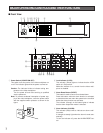
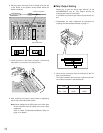
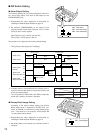
■ DIP Switch Setting
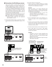
● Alarm Output Setting
The following settings let you set the polarities of alarm out-
put, alarm reset output, and alarm & SW output on the
ALARM/REMOTE port.
1. Disassemble the video multiplexer as described for
installing the Data Multiplex Boards on page 12.
2. Set switches (SW3/SW4/SW5) on the board to the
required position either Open Collector (O.C) or Pulse
(0/5V) for alarm control signals.
Open Collector (O.C): 16V DC 100 mA max.
Pulse (0/5V): +5V DC approx. 500 ms
The positions in the figure are the factory default setting.
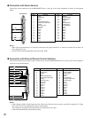
• Timing Table of the signals (0/5 V settings)
0/5V O.C
SW5
0/5V 0/5V
SW3
O.C
SW4
O.C
SW3 : Alarm Output
SW4 : Alarm Reset Output
SW5 : Alarm & SW Output
0VHi-Z Hi-Z Hi-Z
100 ms or more
Approx 100 ms
Approx.
450 ms
Alarm output time
0V
Alarm output time
C
Hi-ZHi-Z 0V
100 ms or more
Retrigger
5V
Alarm output
(Pin #9)
Alarm input 1
Alarm input 2
0V
5V
Alarm reset
output (Pin #27)
0V
5V
Alarm & SW
Output (Pin #25)
0V
SW1
OFF
SW1 : Record Output
O.C position
0/5 V position
Terminal condition
SW
OFF
Hi-Z
0 V
ON
0 V
5 V