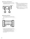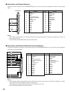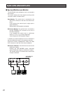
22
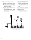
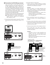
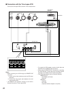
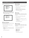
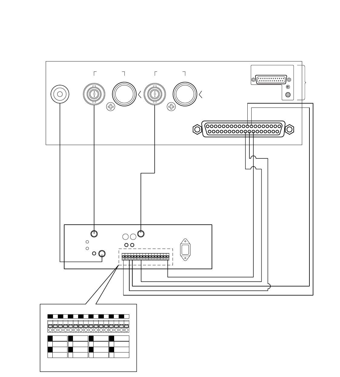
■ Connection with the Time Lapse VCR
Connect the time lapse VCR as shown in the example below.
19
20
1
ALARM/REMOTE
37
CAMERA
SW IN
REC OUT PLAY IN
VIDEO S–VIDEO S–VIDEOVIDEO
VIDEO IN
CAMERA
SW OUT
GND
S-VIDEO
AUDIO
VIDEO OUT
1 2 3 4 5 6 7 8 9 10 11 12 13 14 15 16
89
28 26
134 7 16
1
2
3
4
ALARM
IN
COM
ALARM
RESET IN
ALARM
RECOVER OUT
5
6
7
8
ALARM
OUT
1 SHOT IN
TAPE END
OUT
9
10
11
12
WARNING
OUT
HUMID OUT
REC REVIEW
OUT
13
14
15
16
SERIES
REC IN
TIME
ADJUST IN
TIME
ADJUST OUT
COM REC OUT
SERIES
REC OUT
Video Multiplexer
WJ-FS616C
Time Lapse VCR
VCR CONTROL
R2–232C
REMOTE
OUT
See Notes
Notes:
• Before controlling the VCR through the REMOTE OUT
connector:
1. Power up the video multiplexer and the VCR simul-
taneously.
2. Connect the video signal cable between the multi-
plexer and the VCR.
• The REMOTE OUT performs similarly to the AG-A11
Remote Controller for Time Lapse VCRs.
• To control the VCR remotely, connect it with either the
RS-232C Port or REMOTE OUT Connector.
• When using the REMOTE OUT Connector for controlling
the VCR remotely, reverse play and recording duration
operations are disabled due to system designation.
• The VCRs shown below can be controlled remotely.
<REMOTE OUT>
AG-RT600A, AG-TL500
AG-6124
<RS-232C>
AG-6740*
AG-TL500
(*Optional interface adapter is required)


