


18
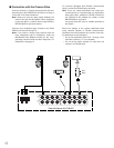
■ Connections for RS-485 type camera
There are two options to connect the camera with the
multiplexer, depending on the distance between them.
For data multiplexed type cameras, a maximum dis-
tance of 900 meters (3 000 ft) is the limit for using coax-
ial cable such as RG-59/U, BELDEN 9259 or equivalent.
If more distance is required, use cameras and multi-
plexer with RS-485 communication feature. This will
lower signal loss and extend the distance as video sig-
nal and data are transmitted separately.
Note that you need to set up the communication port as
described on page 42 when using the RS-485 feature.
Note: Recommended for RS-485 communication is
shielded, two-wire, twisted pair, low impedance
cable, AWG#22 or thicker.
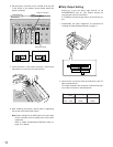
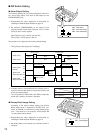
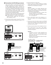
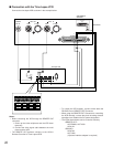
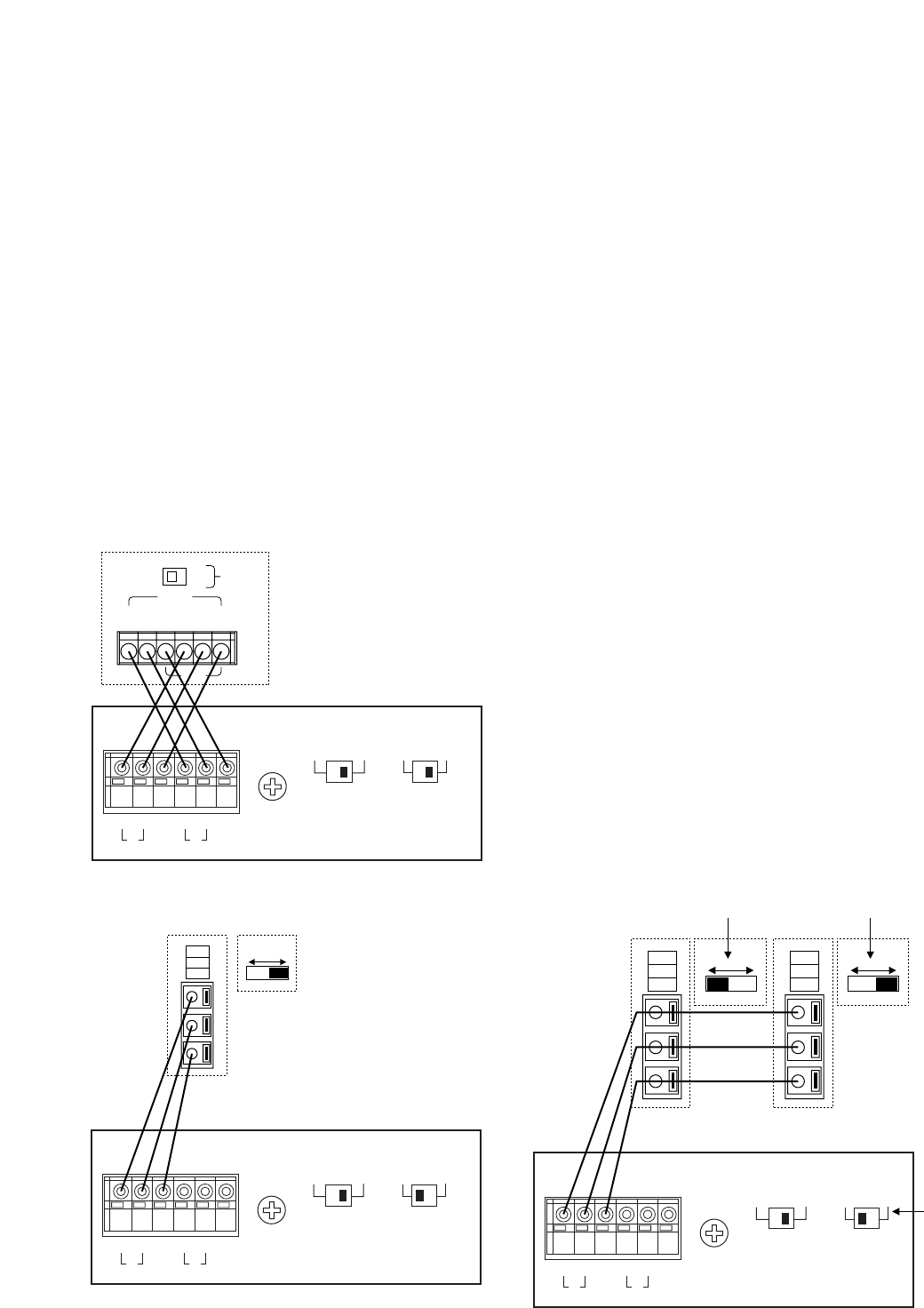
(1) Connect with a RS-485 camera in “Home Run” wiring as
shown below, then set the LINE SELECT switch to “2” or
“4”.
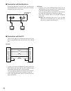
(2) Connect cameras in a Daisy Chain
1. Draw up a plan for connection between the cameras
and the input channels of the video multiplexer, and the
assignment of unit addresses to cameras.
Cautions:
Check the settings of the camera addresses when
using cameras capable of RS-485 communication.
Operations from the multiplexer will not work if the cam-
era addresses are set improperly.
• Do not use addresses other than 1 through 16 for
individual cameras (“17” is not allowed).
• Do not set a single address for more than one cam-
era in an RS-485 chain.
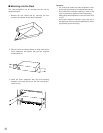
2. Set the LINE SELECT switch of the multiplexer to “2”.
Also set the switch of the connected equipment if
required.
3. Connect one end of the cable as shown to the RS-485
terminal of the multiplexer, and the other end to the first
camera in the chain. Repeat this procedure for all cam-
eras to the end of the chain.
4. Set the termination switches of the multiplexer and cam-
eras at both ends of the chain to ON position.
Termination switches of cameras not at the chain ends
must be in OFF position.
Cautions:
• Termination is the key to data transmission and
reception in the chain. Only the switches at the
chain ends must be set to ON, while the other
switches are set to OFF.
• Response may slow gradually the higher the equip-
ment number in the chain.
ON
OFF
TERM
WJ-FS616C
WV-RM70 and others
GND
DATA
T(A) T(B) R(A) R(B)
A B
T
A B
R
G
N
D
G
N
D
RS485 TERM.
LINE
SELECT
OFF ON 2 4
WJ-FS616C
A B
T
A B
R
G
N
D
G
N
D
RS485 TERM.
LINE
SELECT
OFF ON 2 4
WV-CPR450 and others (For the
Termination Switch positions, refer
to the instruction manual for the
camera.)
(A)
(B)
GND
OFF ON
WJ-FS616C
A B
T
A B
R
G
N
D
G
N
D
RS485 TERM.
LINE
SELECT
OFF ON 2 4
(A)
(B)
GND
OFF ON
(A)
(B)
GND
OFF ON
WV-CPR450 and others
Set it to
position 2
The switch on a daisy-
chain-connected unit not
at the extremities must
be in the OFF position.
The switch on the end
unit should be in the
ON position.
(For the Termination
Switch positions, refer
to the instruction
manual for the
corresponding unit.)