


13
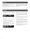
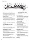
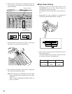
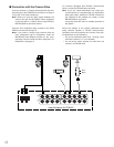
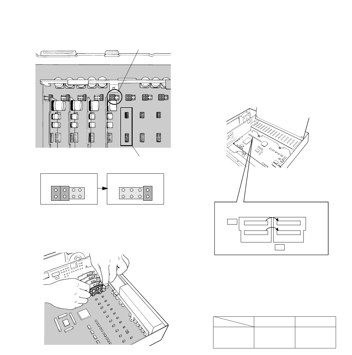
■ Tally Output Setting
Allows you to use the Alarm Input terminal on the
ALARM/REMOTE port as Tally Output terminal by
changing two internal connections.
It is enabled use that mingles alarm input and tally out-
put.
1. Disassemble the video multiplexer as described for
installing the Data Multiplex Boards on page 12.
2. Move the two connectors from the ALM side to the TLY
side as shown above.
The relation between the connector numbers and chan-
nel numbers is shown in the table below.
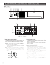
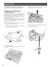
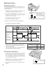
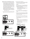
6. Set the jumper connector, that is located at the top left
of the board, to the position shown below where the
board is installed.
7. Insert the board in the board connector. Confirm that
the position is correct and it is placed firmly.
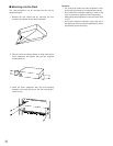
8. After installing the boards, secure them by tightening
the screws and knobs shown above.
Note: Some settings for the VD2 signal and control data
will be necessary from the setup menu of the video
multiplexer.
Refer to Cable Compensation/VD2/Data Setup on
page 41 for details.
Jumper Connector
Board Connector
Initial State Installed State
2
1
8
7
2
1
8
7
CH9 - CH16
CH1 - CH8
10 1
CN33
91
CN32
ALM
TLY
10 1
CN37
91
CN36
Alarm Input
CN33
CN32
Tally Output
CN37
CN36