4-19
Servicing Precautions
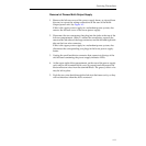
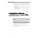
5. Connect the blue AC power wire to the left screw on the AC power
terminal block.
6. Connect the brown AC power wire to the center screw on the AC
power terminal block.
7. If this is the +5 volt supply in a non-redundant power system or the lower
+5 volt supply in a redundant power system, perform Step 8 through
Step 10.
8. Connect the heavy red wire to the left stud.
9. Connect the heavy black wire to the right stud.
10. Replace the lockwashers and nuts and torque to 80 inch pounds.
WARNING
Insufficient torquing of the nuts may cause overheating of the terminals
which could result in fire. However, excessive torquing of the nuts may break
the studs.
11. If this is a non-redundant power system:
a. Before applying power you must set the BYPASS/PROTECT
jumper in the rack fan assembly as described in Section 2 of this
manual.
b. Adjust the power supply voltages as described in the Primary and
Redundant Power Supply Voltage Adjustments procedure in
Section 2 of this manual.
c. You may now reinstall the cover on the rear of the frame, reconnect
the power source, and apply power.
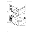
NOTE:
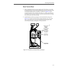
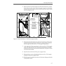
Refer to Figure 4-8 when performing the following step.
12. If this is the upper +5 volt supply in a redundant system:
a. Place the wiring from the signal processor frame over the power
supply studs (red to the left; black to the right), install the
lockwashers and second set of studs, and torque these studs to 80
inch pounds. See WARNING above.
b. Place the wiring to the lower supply over the second set of studs,
install the lockwashers and nuts, and torque the nuts to 80 inch
pounds.


