2-9
Installation
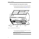
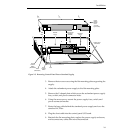
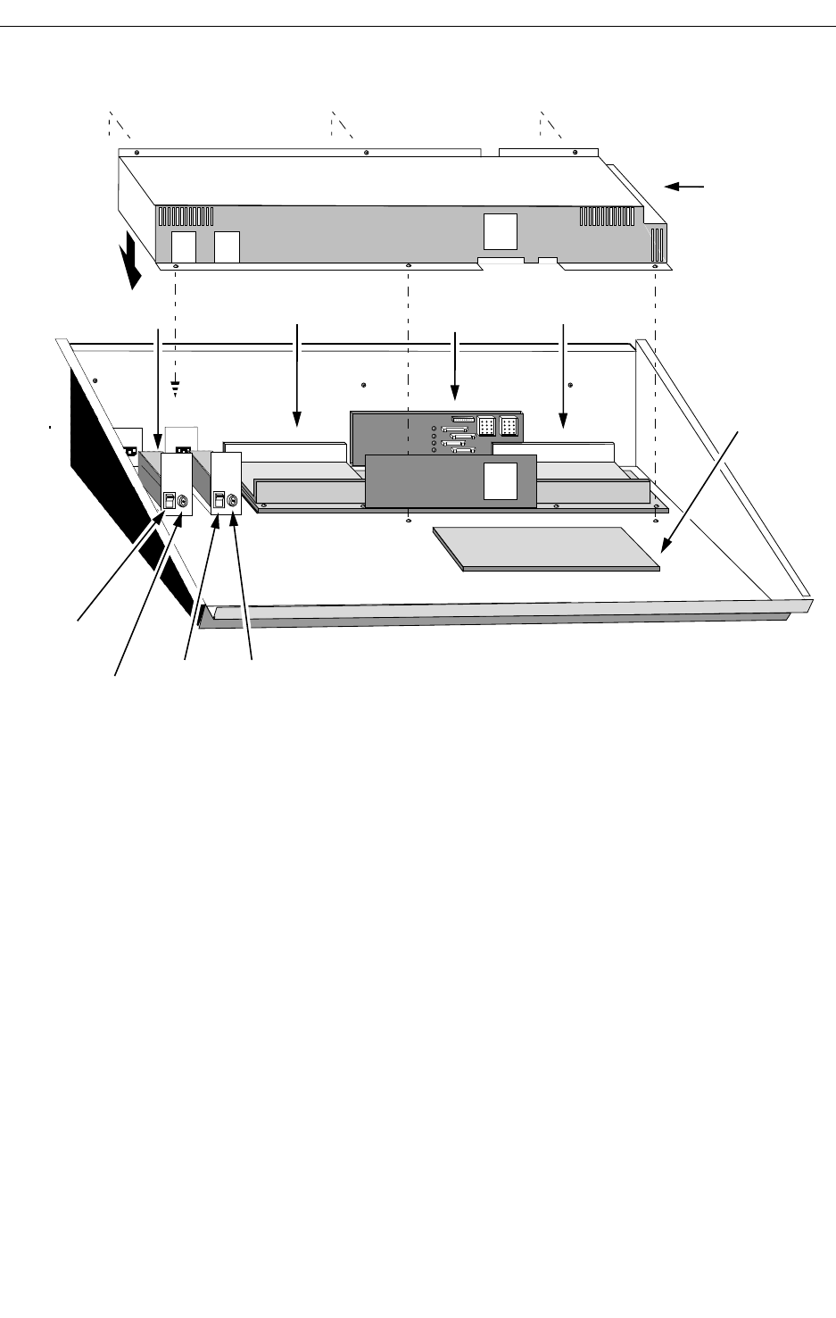
3. Remove the ten screws securing the flat mounting plate supporting the
supply.
4. Attach the redundant power supply to the flat mounting plate.
5. Remove the U shaped plate which covers the redundant power supply
fuse, switch, and power connector holes.
6. Using the same screws, mount the power supply fuse, switch, and
power connector bracket.
7. Route the long cable behind the standard power supply and over the
standard AC filter.
8. Plug the short cable into the control panel I/O board.
9. Reattach the flat mounting plate, replace the power supply enclosure,
and reconnect any cables that were disconnected.
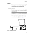
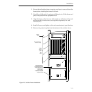
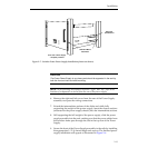
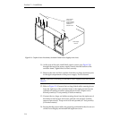
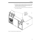
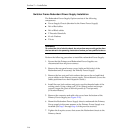
Figure 2-5. Removing Control Panel Power Standard Supply.
Control Panel
CPU Board
Power
ON/OFF
Switch
Fuse
Standard
Supply
Redundant
Supply
Control Panel
I/O Board
(068949)
EMI
Filter
Power
ON/OFF
Switch
(Redundant)
Fuse
(Redundant)
Power
Supply
Access
Cover
(secured
by 6 screws)
Fan


