2-54
Section 2 — Installation
The system defaults to all Aux Buses being part of the [MISC] E-MEM level.
When an Aux Bus is configured for use with an external DPM, its settings
are no longer saved in the [MISC] level but are saved in the relevant [DPM]
level when an E-MEM register is learned. Information (such as Aux Bus
crosspoint selection) is learned for each DPM on separate E-MEM levels.
In cases where it is not desirable to have an Aux Bus selection learned or
recalled on the [MISC] level, it is possible to configure the Aux Bus to a
[DPM] level (such as [DPM 4]) and never enable that level. An example
would be if the Aux Bus were controlled by a Remote Aux panel.
DPM Capabilities (Fixed and Pooled)
The characteristics of the DPM are configured in the DPM Setup menu. The
first choice to be made is selection of
[DPM TYPE] from NONE, KSCOPE, KRYSTAL,
or
OTHER FIXED.
The
[DPM TYPE] of NONE indicates that there is no external DPM device used
for the particular DPM level. However, it can also be used for cases where
Aux Buses are assigned to a DPM level, but there is no physical device, no
return signal, and no control connection (for example, an Aux Bus
dedicated to feeding a video monitor).
Both
KSCOPE and KRYSTAL are selections for pooled devices.
A pooled device is one which provides acquisition of logical channels from
a pool of physical channels.
Kaleidoscope is a pooled device. As an example, consider a Kaleidoscope
having 5 physical channels named A, B, C, D, and E. The pooled channels
are shared by different users. A user may build a Kaleidoscope effect using
3 channels. On one day he may acquire physical channels C, D, and E as
logical channels 1, 2, and 3; on another day he may acquire physical
channels B, C, and D as logical channels 1, 2, and 3. The same effect will
perform identically on both configurations since the operator’s view of the
system is the logical arrangement of channels (1, 2, and 3), not the physical
channels used.
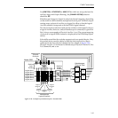
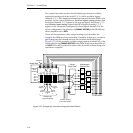
In systems with multiple DPM channels, it is desirable to have a
predictable relationship between Aux Buses and DPM channels (for
example, Aux Bus 1 feeding DPM channel 1, Aux Bus 2 feeding channel 2,
and so on) and to have a particular switcher crosspoint button always
select the same DPM channel return input. For a fixed device (such as the
DPM-700) this relationship is achieved by cabling alone. For a pooled
device, such as Kaleidoscope, the Model 2200 achieves predictable DPM
channel routing by maintaining an extra level of mapping between
physical and logical DPM channels. This mapping, termed Switcher Input
Routing and Switcher Output Routing, is discussed on the following page.


