2-62
Section 2 — Installation
GPI Connections
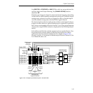
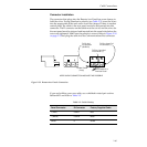
The four GPI connectors on the rear panel of the switcher frame provide
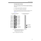
eight input and eight output GPI connections. See Table 2-14 These
connections provide a variety of user-assignable GPI applications such as
remote control of Auto Transitions, DSK mix, Fade-to-Black Transitions
and other selected functions. Refer to “External Interface Setup” later in
this section for defining GPI inputs.
NOTE:
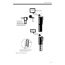
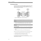
It is important that the shields of the GPI cables be attached to the ground
lugs as shown in Figure 2-31.
GPI Inputs
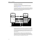
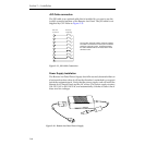
GPI inputs are opto-isolators. These pairs of input connectors are
numbered 1 through 8 with a chassis ground connection on the bottom
and +5V connection on the top end of each connector module. To
trigger the GPI input, a DC voltage must be applied across the pair of
terminals for that input. Voltage must be between 4V and 24V, either
polarity. When the device used to trigger this input has a pair of relay
contacts available, the following wiring connection is recommended
(Input 6 shown in the following example).
Connect the appropriate GPI DC input signals to the GPI INPUTS
connectors TB1 and TB2. See Table 2-31
GPI Outputs
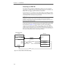
Each GPI output consists of pairs of connections on the rear of the
frame, which are connected to an isolated pair of relay contacts (SPST;
normally open). These pairs of output connectors TB 3 and TB 4 are
numbered 1 through 8 with a chassis ground connection on both ends
of each connector module. These relay connections are rated at 500mA
(peak) for voltages not to exceed 30 volts peak (AC or DC) with respect
to chassis ground.
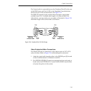
Connect the appropriate GPI output connections to GPI OUTPUTS
connectors TB3 and TB4. Record these output connections for use by
the operator when attaching the triggers to E-MEM recalls.


