2-29
Switcher Option Module Installation
4. Remove the Program DAC Mezzanine board from the Analog Output
Module, and turn the module to the component side. Locate jumpers
J5, J6, J9, and J11; set all four jumpers to either “a” for Color Difference
format, or “b” for RGB format.
5. Locate jumpers J4, J8, and J10 on the Program DAC Mezzanine.
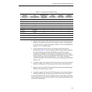
Referring to Table 2-2, set each jumper to the desired format selection
for your analog output format. Note that some formats require
installing two jumpers on J8 and J10. Extra jumpers are stored in an
inactive socket, J7. If you are changing to a format that uses one jumper
at J8 and J10, store the extra jumpers at J7. If you lose a jumper, a
suitable substitute can be made of a short piece of 24 gauge solid tinned
copper wire.
6. Carefully replace the Program DAC Mezzanine on the Analog Output
Module, making sure all connector pins are in the sockets correctly.
7. Remove the Preview DAC Mezzanine board from the Analog Output
Module, and repeat Steps 4, and 5.
8. Carefully replace the Preview DAC Mezzanine on the Analog Output
Module, making sure all connector pins are in the sockets correctly.
Coarse adjustment of the format voltage levels are set by jumper selection;
however, you may need to fine tune these levels using the gain adjustments
on the DAC Mezzanines.
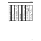
Table 2-2. Analog Output Module Setting
Format
Selection
J16
Analog Module
J5, J6, J9, J11
DAC Mezz.
Color Diff.
J4 (Y)
DAC Mezz.
J8 (R-Y)
DAC Mezz.
J10 (B-Y)
DAC Mezz.
EBU/SMPTE No Setup a a b c
RGB .714 Volts No Setup b b b & d b & d
RGB .714 Volts Setup b c d a & b
RGB .700 Volts No Setup b a a & d b & d
MII 50 Hz No Setup a a c c
MII 60 Hz No Setup a a c e
MII 60 Hz Setup a c c e
Beta 50 Hz No Setup a a d d
Beta 60 Hz No Setup a b d d
Beta 60 Hz Setup a c d d


