1-9
Physical Description
Physical Description
Model 2200 Series electronic circuitry is contained on circuit modules in the
switcher frame, effects frame, and control panel.
In this manual and in other related documents, the circuit modules will be
referred to by the names and assembly numbers printed on them.
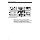
Control Panel
The control panel is the operator interface for the Model 2200 system and
provides all operator controls for the switcher and effects systems.
Through the control panel, the operator performs all actions via
mechanical buttons and controls, or through software controlled menus
and soft button adjustments. The control panel provides the data links to
both Frames.
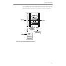
Switcher Frame
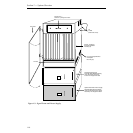
The switcher frame is a large rack-mounted unit, see
Figure 1-3
, that houses
all of the signal processing modules along with some control processor
modules.
The Head-of-State (HOS) processor and all M/E processors reside on two
Control Processor modules in Bay A (front bay) of the frame. Control
Processor 1 contains the HOS processor which supervises the state of the
switcher, handles communication with the control panel and controls the
video hardware. The M/E 1 processor also resides on this module.
The Control Processor 2 contains the circuitry for communication with the
editor, tally expansion and other remote control. The M/E 2 processor is on
this module.
Since each M/E has its own processor, failure of the HOS processor does
not shut down the entire switcher. Individual M/Es can continue to
operate independently, although in a degraded capacity (cuts, mixes and
fade- to-black continue to operate).
The control panel communicates with the switcher frame over two RS-422
data links, one per M/E. Both of the links is contained within a single cable
that may be up to 1000 feet long.


