2-5
Installation
Installation
The following procedures contain the instructions necessary to install the
control panel, switcher frame, and frame power supply. Procedures are
also included for optional circuit modules and cable installation. Before
proceeding, read and understand all precautions and notes.
Control Panel Installation
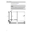
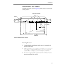
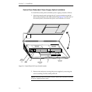
This installation does not require countersunk or beveled edges. The tub
slips into the cutout from the top and is held in place by an overhanging lip
secured by six screws. To install the control panel in the console, proceed
with the following steps.
NOTE:
The control panel should be installed on as flat a surface as possible. It is
not recommended to have more than a 10 degree tilt, as this would add excessive
weight on the gas shocks supporting the control panel top.
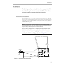
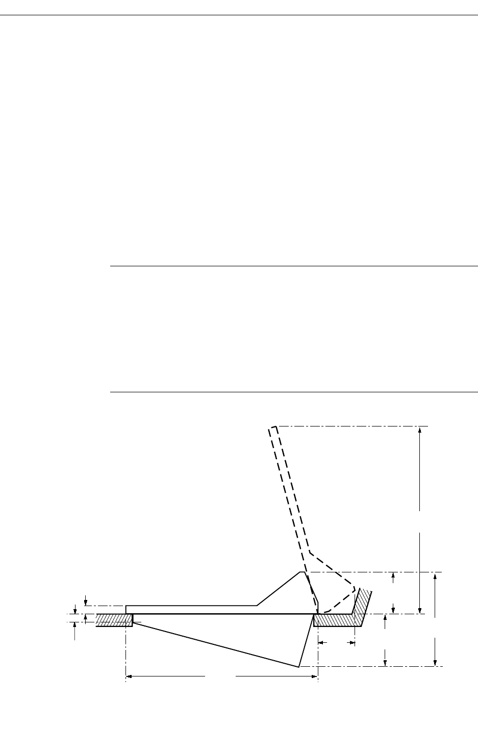
Be sure to leave a minimum of 6.0” (153 mm) of clear space inside the console
behind the control panel for control, signal, and power cables and connectors.
Also, be sure to leave a minimum of 5.2” (152 mm) of clear space behind the
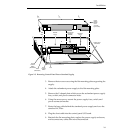
control panel so the lid can be fully opened, as shown in Figure 2-1.
Figure 2-1. Model 2200 Control Panel Profile
23.5"
(596 mm)
2.2"
(56 mm)
1"
(25 mm)
8.0"
(203 mm)
23.5"
(597 mm)
5.2"
(152 mm)
5.8"
(146 mm)
13.8"
(350 mm)


