2-60
Section 2 — Installation
Connecting to a DPM–700
The Model 2200 can initiate E-MEM Effects Memory Learn and Recall
operations in a DPM-700 using Peripheral Bus II protocol. In addition, the
Model 2200 can trigger specific functions in the DPM.
Communication is controlled from the Model 2200 to the DPM; the DPM
will not control or communicate with the Model 2200. (Direct DPM control
of the Model 2200 Aux buses is not provided.)
NOTE:
This interface requires that the Serial Communications mezzanine board
(068918) be installed on the switcher Expanded Communication Module
(068824). The Expanded Communications Module is located in slot B1 and B2 in
the rear bay of the switcher frame.
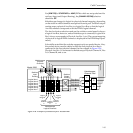
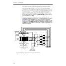
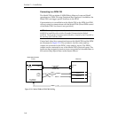
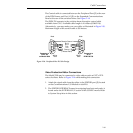
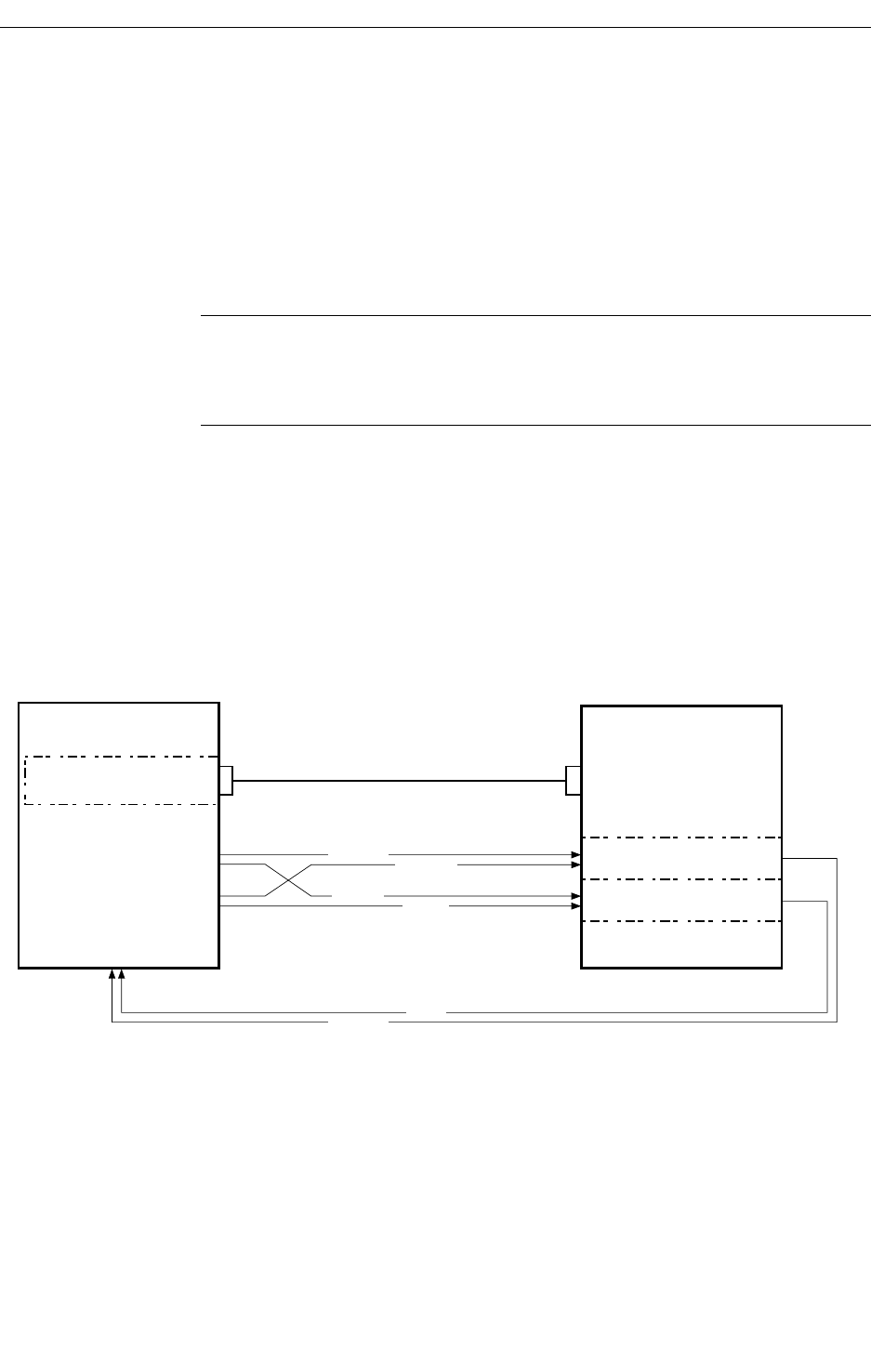
Control and video/key connections between the Model 2200 and the DPM
are illustrated in Figure 2-29. The switcher’s Aux Bus video and key
outputs are connected to the DPM’s video and key inputs. The DPM’s
outputs can be connected to any of the Model 2200’s physical inputs. The
inputs are then assigned via menus to any crosspoints, as described later in
this section (Map Inputs Menu under Inputs Menu).
Figure 2-29. Model 2200 to DPM-700 Cabling
Control Cable
RS-422
(054602-XX)
Port A3
J5
Comm.
Panel
Model 2200 Switcher
Frame
DPM-700
Peripheral
Port
J5
Channel 1
Channel 2
Any
Aux Bus
Outputs
Any Video &
Key Inputs
VIDEO
KEY 1
VIDEO 1
KEY
KEY 2
B
B
A
VIDEO 2


