2-52
Section 2 — Installation
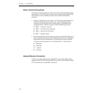
Switcher Communications Connections
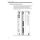
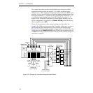
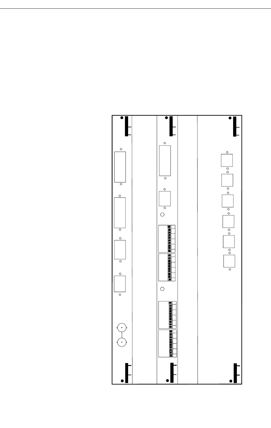
You can connect external devices such as Kaleidoscope, DPM-700, Video
Production Editors, GPI connections, Tally Expansion, and a maintenance
terminal to the switcher. These are connected to the switcher via the
Communications I/O Module, GPI Module and the Expanded
Communications Module, located at the rear bay of the switcher frame as
shown in Figure 2-14. (The Tally Module is located in the Tally Expansion
option and is not shown here).
Figure 2-25. Switcher Frame Communications Connections (Control Section)
GPI
EXPANDED
COM
MAINTENANCE
TALLY EXP
1
2
3
4
G
GPI INPUTS
PORT A1
J1
PORT B1
J2
PORT A2
J3
PORT B2
J4
PORT A3
J5
PORT B3
J6
J1
+5
J2
1
2
3
4
G
+5
TB1
TB2
GPI OUTPUTS
TB3
1
2
3
4
G
TB4
1
2
3
4
G
C1C2
C4C10
G
G
COM
I/O
PANEL
EDITOR
AUX BUS
CTL
ANALOG
REF IN
J1
J2
J3
J4
J5
J6


