2-41
Switcher Option Module Installation
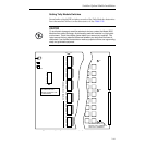
Setting Tally Module Switches
Seven banks of eight DIP switches on each of the Tally Modules determine
how that module will act on the data sent to it. See Table 2-20.
CAUTION
To avoid static damage to sensitive electronic devices, protect the Model 2200
Modules from static discharge. Avoid handling switcher modules in a high static
environment. Touch the switcher frame before you remove any modules. This
helps ensure that any potential difference between your body and the frame is
dissipated. If you handle the modules or make any repairs to them, use a grounding
strap and grounded equipment.
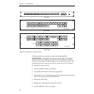
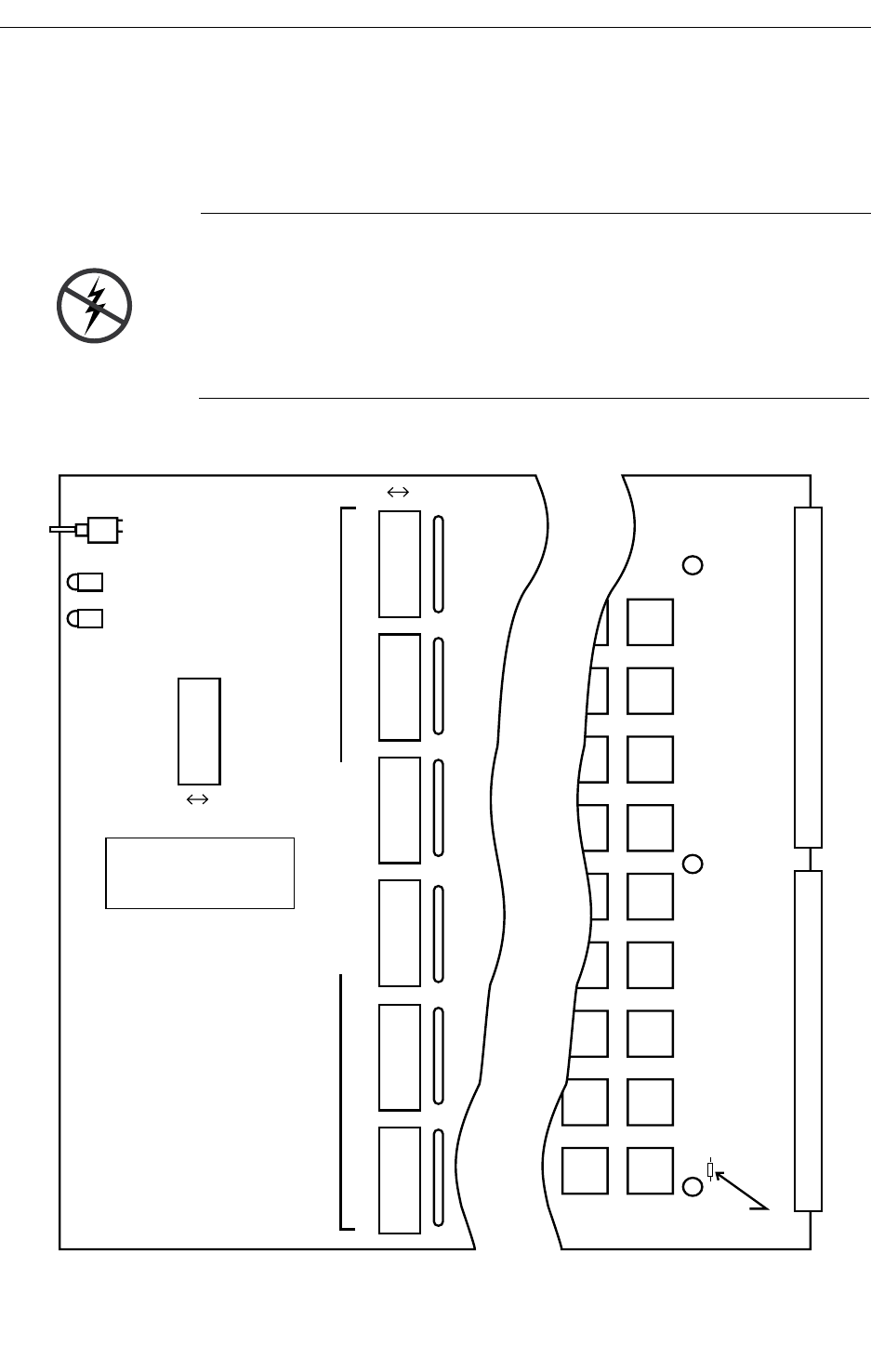
Figure 2-20. Tally Output Module Switch and Jumper Locations
RESET
RUN
INCOMING
DATA
OFF
NORMAL ON-AIR TALLY=
ALL SWITCHES OFF.
REMOVE JUMPER TO
ISOLATE TALLY COMMON A
AND TALLY COMMON B
REFER TO MANUAL FOR
OTHER MODES.
1
2
3
4
5
6
7
8
ON
S2
1
2
3
4
5
6
7
8
OFF ON
S3
9
10
11
12
13
14
15
16
S4
17
18
19
20
21
22
23
24
S5
25
26
27
28
29
30
31
32
S6
33
34
35
36
37
38
39
40
S7
41
42
43
44
45
46
47
48
INDIVIDUAL BUS ENABLES
F3
F2
F1


