4-24
Section 4 — Maintenance
Control Panel Servicing
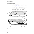
The control panel is divided into two main areas, referred to as the Upper
Panel and the Lower Panel. The location of the components in these two
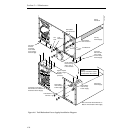
areas are illustrated in Figure 4-11.
The following servicing procedures provide general precautions and
procedures for removing and replacing typical types of components and
assemblies. Detailed procedures are provided only where a component or
module is unique or requires special handling, tools or test equipment.
Figure 4-11. Standard Control Panel Parts Locations.
Lower Control
Panel PuP
066267
Lower Left
Switch Board
066263
3.5"
Floppy
Disk Drive
Lower Center
Switch Board
066264
Lower Right
Switch Board
066265
Positioner
Joystick
(073890
Upper Right
Switch Board
066270
Upper Control
Panel PuP
066271
Upper Left
Switch Board
066268
Upper Center
Switch Board
066269
Model 2200-2i
Control Panel
CPU Board
066272
Power
Supply
Power
Switch
& Fuse
Redundant
Power Switch
& Fuse
Power Supply
(Standard)
Power Supply
(Redundant)
Display
Board
(hidden)
066262
Model 2200-2s
Control Panel
CPU Board
068960
Control Panel
Power Supply
Cover


