2-68
Section 2 — Installation
Tally Expansion Option
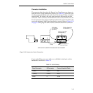
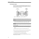
The Tally Expansion Control Cable installation information follows. Each
chassis comes with a 16 meter (50 foot) cable. This cable has a 9 pin D
connector on each end. The cables are standard RS422 and can be replaced
with a custom-built cable if desired.
NOTE:
Maximum total length of the tally expansion cables is 300 meters
(1000 feet)
1. Locate J2 on the GPI Module at the rear of the switcher. Tie cable so the
connector on the cable will reach the connector on the switcher.
CAUTION
Do not plug the cable into the switcher at this time. Doing so may damage the line
drivers in the switcher.
2. Lay the cable from the switcher chassis to the first Tally Expansion
option.
3. Plug this cable into J3 on the rear of the Tally Expansion unit.
If there is more than one Tally Expansion chassis, do the following steps:
1. Connect the second cable to J4 on the rear of the first chassis.
2. Run that cable to the next Tally Expansion chassis.
3. Connect cable to J3 on the rear of the second chassis.
Repeat the above three instructions for each additional chassis. There are
no terminations for the cable.
Cable Shield and
Chassis Ground
Ground
Connects to
J2 on GPI Module
1
2
6
7
3
8
4
9
5
Rx B
Tx A
Tx B
Male
(Twisted Pairs)
Rx A
Connects to
J3 on
Tally Expansion
Frame
1
2
6
7
3
8
4
9
5
Male
Wiring
Side
Wiring
Side
Figure 2-36. Tally Expansion Control Cable Wiring


