2-61
Cable Connections
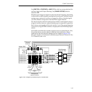
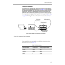
The Control cable is connected between the Peripheral Port (J5) at the rear
of the DPM frame, and Port A3 (J5) on the Expanded Communications
Panel at the rear of the switcher frame. See Figure 2-14.
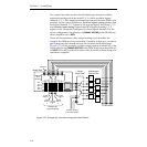
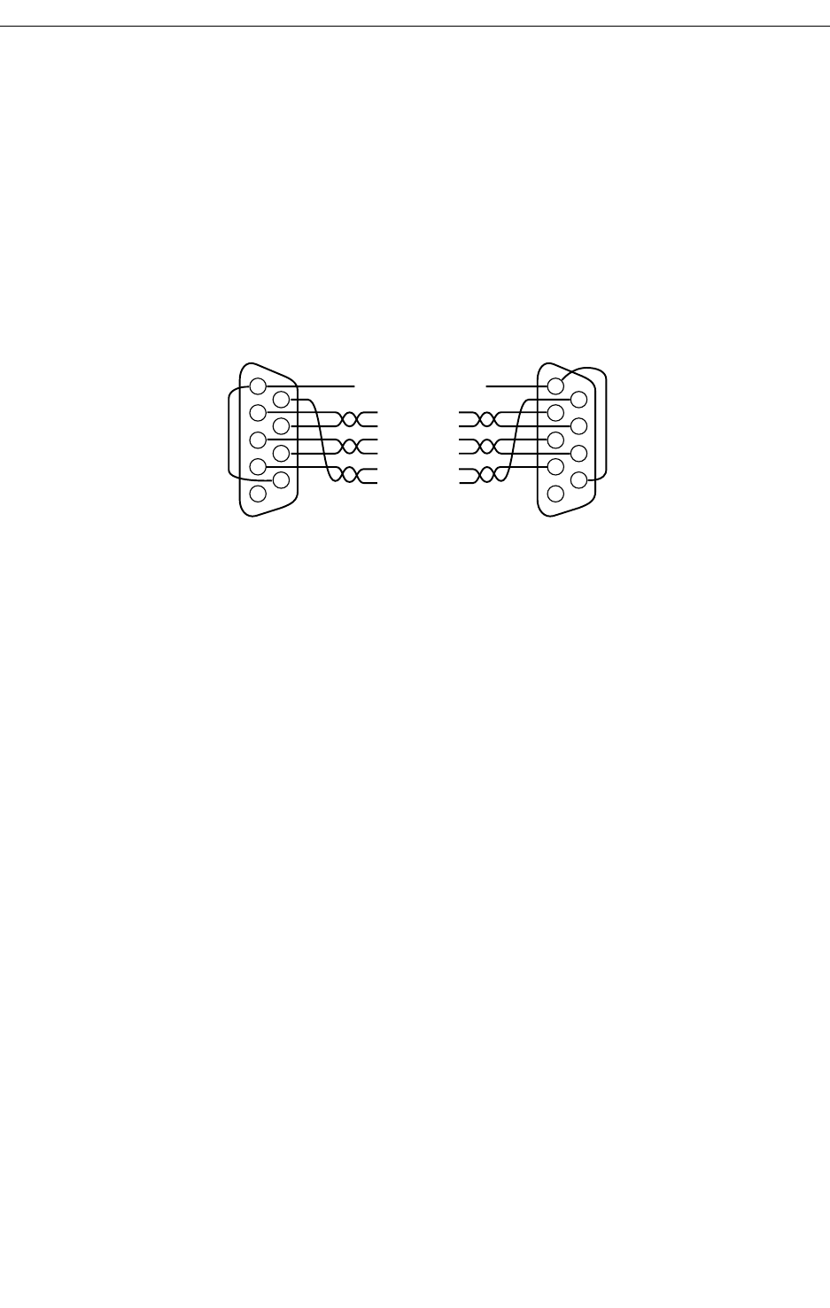
The DPM-700 connects to the switcher frame through a control cable
available from GVG. Available cable length is 16 meters (054602-16).
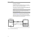
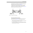
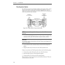
Alternatively, you may make your own cable, as illustrated in Figure 2-30.
Maximum length of the control cable is 300 meters.
Video Production Editor Connections
The Model 2200 may be connected to video editors such as GVP’s VPE-
series of editors. Refer to Figure 2-14 while making this connection.
1. Attach the signal cable from the editor to the EDITOR port (J3) located
on the Communications I/O Module in slot B10.
2. The EDITOR INTERFACE menu for assigning baud rate and parity is
found under the EXTERNAL I/F section of the CONFG menus. Refer
to System Setup later in this section.
Figure 2-30. Peripheral Bus II Cable Design
Chassis Ground
Ground
Connects to
PORT A3
on Model 2000
1
2
6
7
3
8
4
9
5
Rx B
Tx A
Tx B
Male
(Twisted Pairs)
Rx A
Connects to
J5 on
DPM 100/700
1
2
6
7
3
8
4
9
5
Male
Wiring
Side
Wiring
Side


