4-21
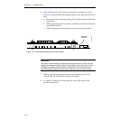
Fan Jumper Setting
13. If this is a redundant power system:
a. You must replace the +5 Volt power assembly in the second Power
Supply frame (if it is not a Todd supply) by repeating the
procedures listed above.
b. Before applying power you must set the BYPASS/PROTECT
jumper in the rack fan assembly as described in the Installation
information in Section 2 of this manual.
c. When you have completed the installation (of both +5 Volt
supplies, if required), reconnect the power source and apply power
to both units.
Before you install the rear plates on the Power Supply frames, you must
check the output voltages for load-sharing, as described in the Installation
information in Section 2 of this manual.
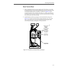
Fan Jumper Setting
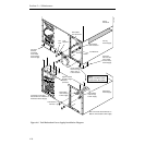
There is a jumper on the small circuit board (064851) in the fan assembly at
the top of the rack for Model 2200 Switchers. This jumper must be in the
correct position for proper operation of these switchers.
1. Loosen the retaining screws of the fan assembly and pull the assembly
out of the rack.
2. Check the position of the BYPASS/PROTECT jumper.
a. For the Todd +5 Volt power supplies, set the jumper to the BYPASS
position. The Todd supplies have internal protection. They will not
operate with the jumper in PROTECT mode.
b. For the Pioneer +5 Volt power supplies, set the jumper to the
PROTECT position. The jumper, in PROTECT position, is intended
to prevent a harmful surge should the Pioneer +5 V supply be
accidentally shorted.


