


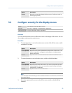
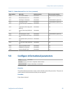
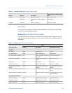

Default settings for mA Output Process VariableTable 6-1:
Device Channel mA output
Default process variable assign-
ment
FVM mA Channel A Primary mA output Kinematic viscosity
Channel B Secondary mA output (if applica-
ble)
Temperature
FVM DO Channel A Primary mA output Kinematic viscosity
Postrequisites
If you changed the setting of mA Output Process Variable, verify the settings of Lower Range
Value (LRV) and Upper Range Value (URV).
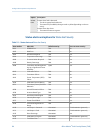
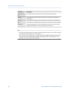
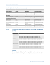
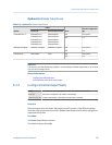
Options for mA Output Process Variable
The transmitter provides a basic set of options for mA Output Process Variable, plus several
application-specific options. Different communications tools may use different labels for
the options.
Options for mA Output Process VariableTable 6-2:
Process variable
Label
Display ProLink III Field Communicator
Standard
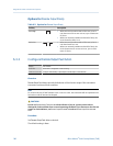
Line Density DENS Line Density Density
Line Temperature TEMP Line Temperature Temperature
Line Temperature (External) EXT T Line Temperature (External
or Fixed)
External Temperature
Line Pressure (External) EXT P Line Pressure (External or
Fixed)
External Pressure
Drive Gain DGAIN Drive Gain Drive Gain
Sensor Time Period TP B Sensor Time Period Sensor Time Period
User-Defined Calculation
Output
UCALC User-Defined Calculation
Output
User-Defined Calculation
Output
Volume Flow Rate (External) MAG V Volume Flow Rate (External) Volume from Mag/Vortex
Meter
Mass Flow Rate (Calculated) MAG M Mass Flow Rate (Calculated) Calculated Mass Flow from
Mag Meter Input
Viscosity measurement
Dynamic Viscosity DYNV Line Dynamic Viscosity Dynamic Viscosity
Kinematic Viscosity KINV Line Kinematic Viscosity Kinematic Viscosity
Referred Viscosity RVISC Referred Viscosity Referred Viscosity
Integrate the meter with the control system
Configuration and Use Manual 99