


e. Verify the signal at the receiving device.
f. At the transmitter, activate Select.
3. Test the TPS output.
a. Attach a frequency counter, oscilloscope, digital multimeter (DMM), or digital
voltmeter (DVM) to the TPS output loop.
b. Compare the reading to the Sensor Time Period process variable at your meter.
Postrequisites
• If the mA output readings are within 200 microamps of each other, you can correct
this discrepancy by trimming the output.
• If the discrepancy between the mA output readings is greater than 200 microamps,
or if at any step the reading was faulty, verify the wiring between the transmitter
and the remote device, and try again.
• If the discrete output readings are reversed, check the setting of Discrete Output
Polarity.
• If the TPS output readings do not match, contact Micro Motion customer service.
10.4.2 Perform loop tests using ProLink III
A loop test is a way to verify that the transmitter and the remote device are
communicating properly. A loop test also helps you know whether you need to trim mA
outputs.
Prerequisites
Before performing a loop test, configure the channels for the transmitter inputs and
outputs that will be used in your application.
Follow appropriate procedures to ensure that loop testing will not interfere with existing
measurement and control loops.
Procedure
1. Test the mA output(s).
a. Choose Device Tools > Diagnostics > Testing > mA Output 1 Test or Device Tools >
Diagnostics > Testing > mA Output 2 Test.
b. Enter 4 in Fix to:.
c. Click Fix mA.
d. Read the mA current at the receiving device and compare it to the transmitter
output.
The readings do not need to match exactly. If the values are slightly different,
you can correct the discrepancy by trimming the output.
e. Click UnFix mA.
f. Enter 20 in Fix to:.
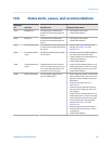
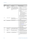
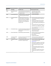
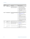
Troubleshooting
Configuration and Use Manual 163