


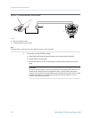
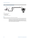
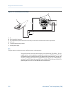


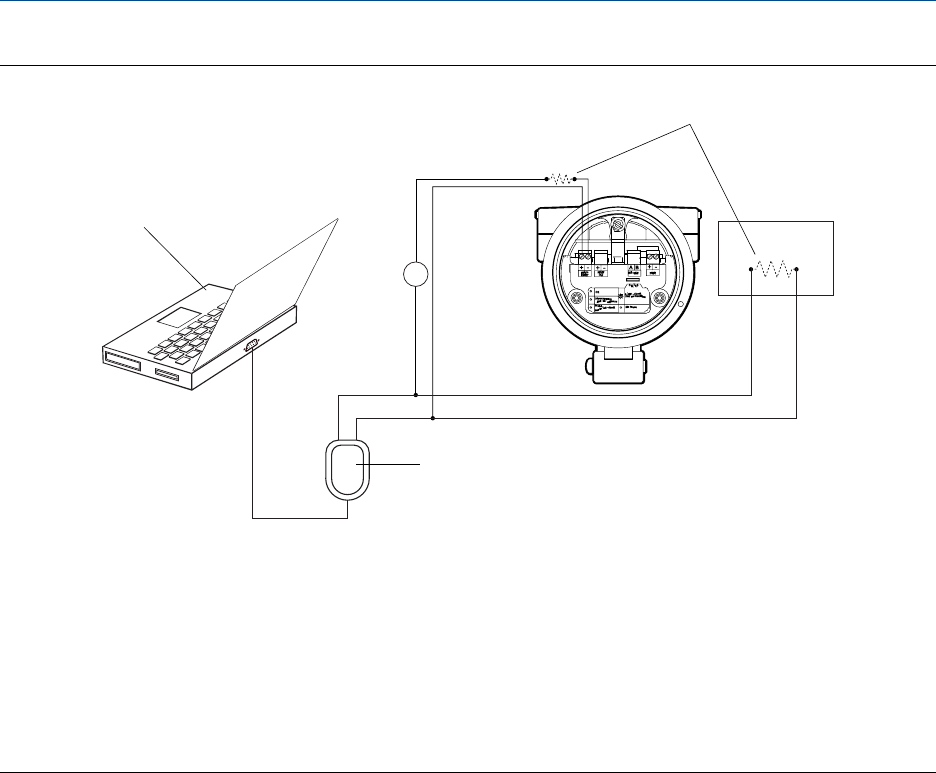
Connection over local loopFigure C-5:
A
C
D
E
F
R1
R2
B
+
–
A. PC
B. RS‐232 to Bell 202 converter
C. Any combination of resistors R1 and R2 as necessary to meet HART communication resistance requirements
D. DCS or PLC
E. Transmitter with end‐cap removed
F. External power supply
Note
This figure shows a serial port connection. USB connections are also supported.
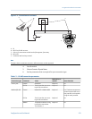
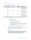
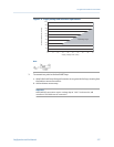
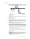
The signal converter must be connected across a resistance of 250–600 Ω. The mA
output requires an external power supply with a minimum of 250 Ω and 17.5 V. See
the following figure to help determine the appropriate combination of voltage and
resistance. To meet the resistance requirements, you may use any combination of
resistors R1 and R2. Note that many PLCs have a built-in 250-Ω resistor. If the PLC is
powering the circuit, be sure to take this into consideration.
Using ProLink III with the transmitter
218 Micro Motion
®
Fork Viscosity Meters (FVM)