


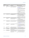
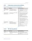

10.14 Time Period Signal (TPS) output problems
TPS output problems and recommended actionsTable 10-6:
Problem Possible causes Recommended actions
No TPS output • The TPS output is not supported on this
device
• TPS wiring is connected to the wrong ter-
minals
• Output not powered
• External short or low input impedance
• Verify that the output loop is powered ex-
ternally.
• Check the power supply and power supply
wiring. See Section 10.2.
• Verify the output wiring.
• Contact Micro Motion.
Loop test failed • Power supply problem
• Wiring problem
• Circuit failure
• Verify that the output loop is powered ex-
ternally.
• Check the power supply and power supply
wiring. See Section 10.2.
• Verify the output wiring.
• Contact Micro Motion.
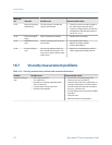
10.15 Using sensor simulation for troubleshooting
When sensor simulation is enabled, the transmitter reports user-specified values for basic
process variables. This allows you to reproduce various process conditions or to test the
system.
You can use sensor simulation to help distinguish between legitimate process noise and
externally caused variation. For example, consider a receiving device that reports an
unexpectedly erratic density value. If sensor simulation is enabled and the observed
density value does not match the simulated value, the source of the problem is likely to be
somewhere between the transmitter and the receiving device.
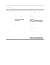
Important
When sensor simulation is active, the simulated value is used in all transmitter outputs and
calculations, including totals and inventories, volume flow calculations, and concentration
calculations. Disable all automatic functions related to the transmitter outputs and place the loop in
manual operation. Do not enable simulation mode unless your application can tolerate these effects,
and be sure to disable simulation mode when you have finished testing.
Related information
Test or tune the system using sensor simulation
Troubleshooting
Configuration and Use Manual 179