


• Stop bits: 1 or 2
• Baud: 1200, 2400, 4800, 9600, 19200, 38400
You do not need to configure these communications parameters on the device.
Procedure
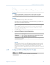
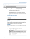
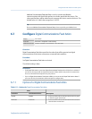
1. Enable or disable Modbus ASCII Support as desired.
The setting of this parameter controls the range of valid Modbus addresses for your
device.
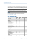
Modbus ASCII support Available Modbus addresses
Disabled 1–127, excluding 111 (111 is reserved to the service port)
Enabled 1–15, 32–47, 64–79, and 96–110
2. Set Modbus Address to a unique value on the network.
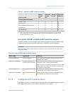
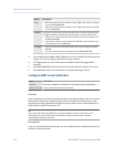
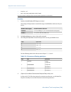
3. Set Floating-Point Byte Order to match the byte order used by your Modbus host.
Code Byte order
0 1–2 3–4
1 3–4 1–2
2 2–1 4–3
3 4–3 2–1
See the following table for the bit structure of bytes 1, 2, 3, and 4.
Bit structure of floating-point bytesTable 6-10:
Byte Bits Definition
1 SEEEEEEE S=Sign
E=Exponent
2 EMMMMMMM E=Exponent
M=Mantissa
3 MMMMMMMM M=Mantissa
4 MMMMMMMM M=Mantissa
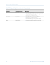
4. (Optional) Set Additional Communications Response Delay in delay units.
A delay unit is 2/3 of the time required to transmit one character, as calculated for
the port currently in use and the character transmission parameters.
Integrate the meter with the control system
116 Micro Motion
®
Fork Viscosity Meters (FVM)