


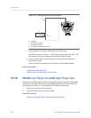
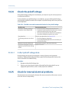

Wiring and power to test terminalsFigure 10-1:
A
B
C
D
A. Voltmeter
B. 250–600 Ω resistance
C. External power supply
D. Transmitter with end‐cap removed
c. Using a voltmeter, check the voltage drop across the resistor.
For a 250 Ω resistor, 4–20 mA = 1–5 VDC. If the voltage drop is less than 1 VDC,
add resistance to achieve a voltage drop within the required range.
d. Connect a Field Communicator directly across the resistor and attempt to
communicate (poll).
If this test fails, the transmitter may need service. Contact Micro Motion.
Related information
Configure basic HART parameters
Using the Field Communicator with the transmitter
10.18 Check Lower Range Value and Upper Range Value
If the process variable assigned to the mA output falls below the configured Lower Range
Value (LRV) or rises above the configured Upper Range Value (URV), the meter will post a
saturation alert (A100 or A113), then perform the configured fault action.
1. Record your current process conditions.
2. Check the configuration of the LRV and URV.
Related information
Configure Lower Range Value (LRV) and Upper Range Value (URV)
Troubleshooting
182 Micro Motion
®
Fork Viscosity Meters (FVM)