


Appendix B
Using the transmitter display
Topics covered in this appendix:
• Components of the transmitter interface
• Use the optical switches
• Access and use the display menu system
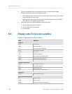
• Display codes for process variables
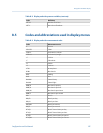
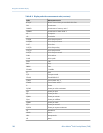
• Codes and abbreviations used in display menus
B.1 Components of the transmitter interface
The transmitter interface includes the status LED, the display (LCD panel), and two optical
switches.
B.2 Use the optical switches
Use the optical switches on the transmitter interface to control the transmitter display.
The transmitter has two optical switches: Scroll and Select.
Procedure
To activate an optical switch, block the light by holding your thumb or finger in front of the
opening.
Tip
You can activate the optical switch through the lens. Do not remove the transmitter housing cover.
The optical switch indicator lights up when the transmitter senses that an optical switch
has been activated.
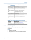
Optical switch indicator and optical switch statesTable B-1:
Optical switch indicator State of optical switches
Solid red One optical switch is activated.
Flashing red Both optical switches are activated.
Using the transmitter display
Configuration and Use Manual 191