


2-5MGP 462 • Installation
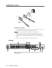
Input connectors
1
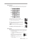
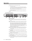
Inputs 1, 2, 3, and 4 — Plug RGB, component video, S-video, or composite
video sources into these BNC connectors as shown in the diagram below.
RGBHV
Video
RGsB or
Component
Video
S-Video
Composite
Video
RGBS or
RGBcvS
Video
H/HV
V
R/R-Y
G/Y
VID
B/C
B-Y
H/HV
V
R/R-Y
G/Y
VID
B/C
B-Y
H/HV
V
R/R-Y
G/Y
VID
B/C
B-Y
H/HV
V
R/R-Y
G/Y
VID
B/C
B-Y
H/HV
V
R/R-Y
G/Y
VID
B/C
B-Y
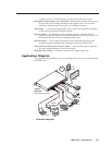
Connector signal types for inputs 1 through 4
2
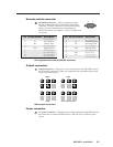
Input 5 — Plug a component video, S-video, or composite
video source into these BNC connectors.
3
Input 6 — Plug an S-video source into the 4-pin mini DIN
connector (in bottom row) or a composite video source into
the VID BNC connector (in top row).
Connecting S-video and composite video devices to input 6
simultaneously causes degraded output display quality.
4
SDI input — (MGP 462D only) Plug an SDI device into this
SDI BNC connector, as an alternative to input 6.
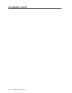
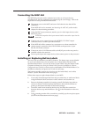
LAN connector
5
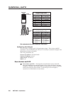
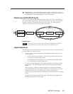
LAN connector — Plug an RJ-45 network cable into this connector to connect
the unit to a network (via a switch, hub, or router) or to a single computer.
Use a straight-through cable to connect to a network, or a crossover cable to
connect directly to a computer.
• For 10Base-T (10 Mbps) networks, use a Cat 3 or better cable.
• For 100 Base-T (max. 155 Mbps) networks, use a
Cat 5 cable.
See the illustration on the next page for information on
wiring the connector for these two types of cables..
Activity LED — This yellow LED blinks to indicate
network activity.
Link LED — This green LED lights to indicate a good
network connection.
LAN
RJ-45
Port
Link
LED
Activity
LED
VID
/Y
5
R-Y
/C
B-Y
VID
6
VID
SDI
6
YC
B-Y
VID
SDI
6
YC
B-Y