


2 Virtual-IO Manager - Introduction
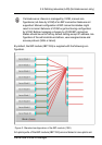
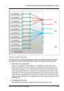
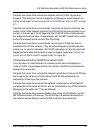
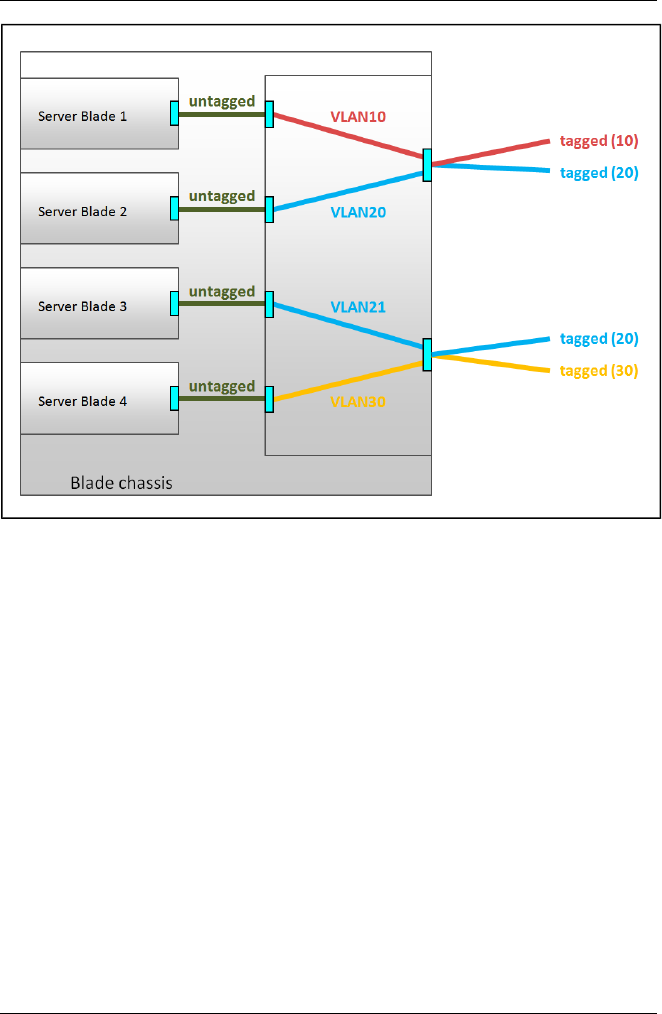
Figure 5: Networks with VLAN ID
In the figure above, two shared uplink sets are configured on the IBP module.
Two virtual networks VLAN10 and VLAN20 with the VLAN IDs 10 and 20
are assigned to the upper shared uplink set, and two virtual networks
VLAN21 and VLAN30 with the VLAN IDs 20 and 30 are assigned to the
lower shared uplink set. Although both uplink sets have virtual networks with
the VLAN ID 20, these are two different virtual networks. Server blade 2 can-
not communicate with server blade 3.
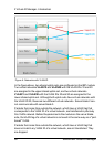
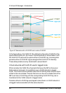
Packets that come from outside the network, which have a VLAN tag that
corresponds to the VLAN ID of a virtual network, are transferred in precisely
this VLAN network. Before the packet exits the module on the server blade
side, the VLAN tag of a virtual network is removed in the same way as a "port-
based" VLAN.
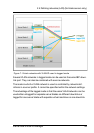
Packets that come from outside the network, which have a VLAN tag that
does not match any VLAN ID of a virtual network, are not transferred. They
are dropped.
36 ServerView Virtual-IO Manager