


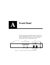

Front Panel
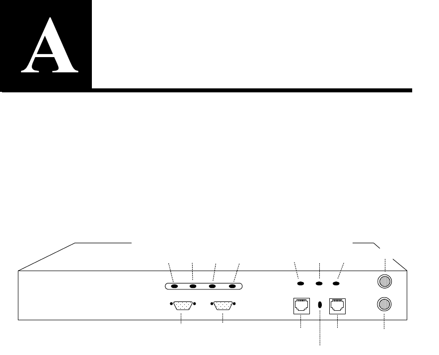
The following diagram shows the LEDs, buttons, switches and con-
nections for the Intel® NetStructure™ 7110/7115 e-Commerce Ac-
celerator. Note that there is no power switch or button. Power is
applied to the device by connecting the power cable.
Figure A-1: Front Panel Connectors, Controls, and Indicators
Bypass
Reset
Network Link
(RJ45)
Server Link
(RJ45)
Inline
(green)
Network Link
(green)
Server Link
(green)
LEDs
Fail-through switch
Console
(CLI)
Aux Console
(Diagnostics)
Power
(green)
Error
(red)
Overload
(amber)
Activity
(green)
LEDs