


85
To use the HDD deck for the recording component:
1
Make connections
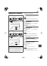
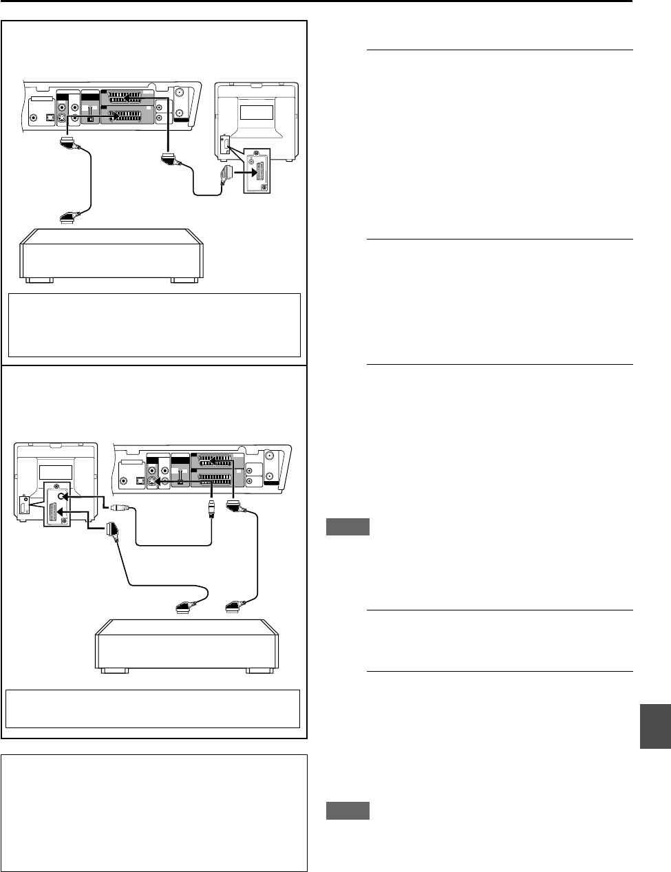
Connect the VCR through the L-2 IN (or L-1 IN/OUT)
connector on the rear using the 21-pin SCART cable (not
supplied).
• When using the L-2 IN connector, set “L-2 SELECT” to
“A/V” (see page 68).
•
If both the external VCR and the TV are compatible
with S-Video signal:
Set “L-1 OUTPUT” or “L-2 INPUT” to “S-VIDEO” (see
page 68).
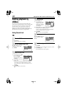
2
Select the HDD deck.
On the remote control
Set the
DVD/TV/HDD
selector set to the right (
HDD
),
then press
ENTER
(or
LIVE
).
On the unit
Press
DVD/HDD
so that the HDD lamp lights.
3
Select the input mode on the HDD deck.
On the remote control
Press
AUX
(
number
button “
0
”) and/or
HDD/TV PR +/–
to select “L-2” for the L-2 IN connection, or “L-1” for the
L-1 IN/OUT connection.
On the unit
Press
PR +/–
to select “L-2” for the L-2 IN connection, or
“L-1” for the L-1 IN/OUT connection.
NOTE
When connecting a TV with TV-Link or with equivalent function
(see page 15) using the SCART cable, select “OFF” for “DIRECT
REC” (see page 67) in order to record S-Video signals through
the L-2 IN connector.
4
Start playback on the VCR.
• Refer to the instruction manual supplied with the VCR.
5
Start recording on the HDD deck.
On the remote control
Press and hold
REC
, then press
3
.
On the unit
Press
(record).
The lamp next to the
(record) button lights.
NOTE
For Y/C signal input/output, be sure to use a 21-pin SCART cable
that is compatible with the Y/C signal.
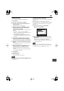
Precaution before editing onto the HDD
The picture shown on the TV is a few seconds
behind the scene currently recorded onto the HDD.
Therefore, if you start recording at the desired scene
on the TV, you will miss the beginning of the scene by
a few seconds. On the other hand, when you stop
recording, you will record some extra scenes.
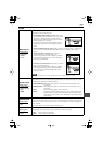
ANTENNA
L-1
VIDEO SIGNAL
SELECTOR
VIDEO
OUT
AUDIO
OUT
L-2
OUT
IN
/
OUT
DVDDVD
/
HDD
SAT CONTROL
AV
COMPU LINK
IN
OPTICALCOAXIAL
DVD DIGITAL OUT
PCM / STREAM
LEFT
RIGHT
IN
Y
/
C
COMP.
/
RGB
S-VIDEO
VIDEO
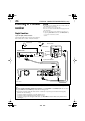
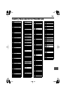
21-pin SCART
cables (not supplied)
XV-DDV1SL
TV
VCR
ANTENNA
L-1
VIDEO SIGNAL
SELECTOR
VIDEO
OUT
AUDIO
OUT
L-2
OUT
IN
/
OUT
DVDDVD
/
HDD
SAT CONTROL
AV
COMPU LINK
IN
OPTICALCOAXIAL
DVD DIGITAL OUT
PCM / STREAM
LEFT
RIGHT
IN
Y
/
C
COMP.
/
RGB
S-VIDEO
VIDEO
Connection to the L-2 IN connector with the SCART
cables
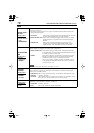
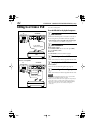
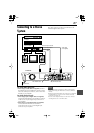
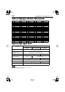
When connecting the VCR to the L-1 IN/OUT
connector:
VCR
TV
XV-DDV1SL
S-video cable
(not supplied)
21-pin SCART
cables (not supplied)
S-Video cable connection is required only when the VCR is
not compatible with S-Video, but the TV is compatible.
The HDD deck is not compatible with RGB signal input. So
do not connect an RGB component to the L-2 IN connector
(or do not set the signal output mode of the connected
component to RGB signal).