


Initial Configuration
26
P2CIM‐APS2(IBMPS/2compatibleservers)or
P2CIM‐APS2‐B(IBMBladeCenterManagementModulewith
PS/2ports):
PlugtheHD15strandintotheserver’sHD15VGAvideoport.
Plugthepurple6‐pinmini‐DINkeyboardstrandintotheserver’s
6‐pinmini‐DINkeyboardport.Plugthelightgreen6‐pin
mini‐DI
Nstrandintotheserver’s6‐pinmini‐DINmouseport.
P2CIM‐ASUN(Suncompatibleservers):
PlugtheHD15strandintotheserver’sHD15VGAvideoport.
Plugthe8‐pinmini‐DINstrandintotheserver’s8‐pinmini‐DIN
keyboard/mouseport.
P2CIM‐AUSB,P2CIM‐AUSB‐C,orP2
CIM‐AUSB‐B(IBM
BladeCenterManagementModulewithUSBports):
PlugtheHD15strandintotheserver’sHD15VGAvideoport.
PlugtheUSBTypeAstrandintooneoftheserver’sUSBTypeA
ports.
P2CIM‐APS2DUAL(IBMPS/2compatibleservers):
Connectkeyboard,monitor,andmouseca
blesattachedtothe
CIMtotheappropriate15‐pinfemalevideoportand6‐pin
mini‐DINmouseandkeyboardportsontheserver.
P2CIM‐SER,P2CIM‐SER‐EUandAUATC(serialservers,
routers,andsoon):
PleaseseeConnectingSerialDevicestoParagonIISystem(on
page188)forinst
allationinstructions.
P2ZCIMandZ‐CIM(localsingle‐userIBMPS/2compatible
servers):
PleaseseeParagonIIandP2ZCIMs/Z‐CIMs(onpage116)for
inst
allationinstructions.
b. Pluginandpowerontheserver.IftheCIMisinstalledand
operatingproperly,theCIM’sgreenLEDwillstartblinking:once
persecondwhiletheCIMisidle,morequicklywhiledatais
transmittedineitherdirection.
c. ConnectoneendofaCat5UTPca
bletochannelport#1onthe
backoftheParagonswitch.Connecttheotherendofthecableto
theRJ45portontheCIM.
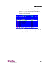
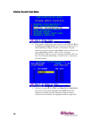
6. ConfiguretheCIMandtheattachedserver.