


Main code Sub code Content
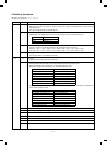
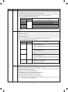
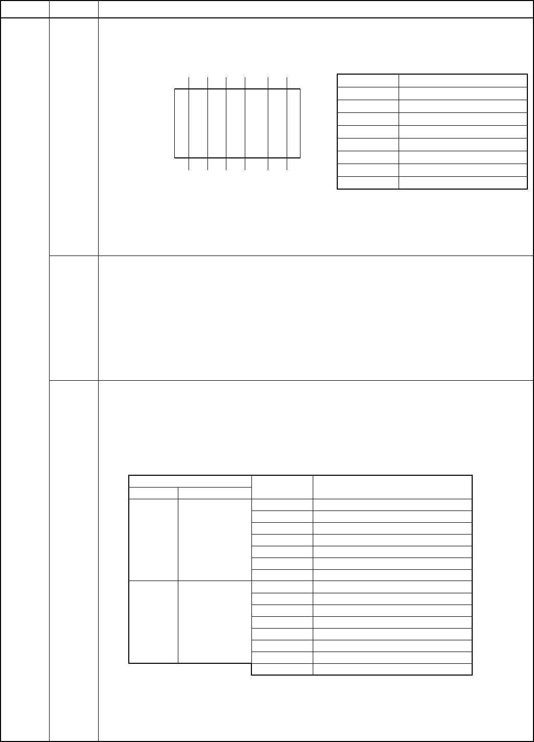
41 01 Original sensor check
Used to display the judgement result of the original sensor on the operation panel LED.
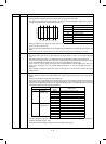
The original sensor values are read sequentially. If the sensor is interrupted (judged as presence of an original),
the LED corresponding to the sensor position is turned on.
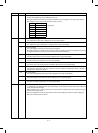
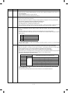
Sensor name Operation panel LED
PD0 Original size LED A5/INV
PD1 Original size B5
PD2 Original size A4/LT
PD3 Original size B5R
PD4 Original size A4R/LTR
PD5 Original size B4/LG
PD6 Original size A3/WLT
OCSW Manual feed tray selection LED
When the original cover is closed, the original sensor is not read and it is judged as no original at all. (All the
original size LED’s are turned off.)
Since the machines for Japan/Taiwan are not equipped with the PD0 sensor, the original size LED display is not
made.
For the other areas, PD1 and PD3 sensors are not provided and the original size LED display is not made.
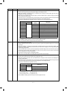
02 Original sensor adjustment
The original sensor input values of original presence and original empty are read to set the original judgement
level.
When this simulation is executed, “1” is displayed on the copy quantity display and the ready lamp lights up.
First, in order to read the original sensor input value of original empty, press the PRINT button without an original
on the original table with the original cover open. The copy quantity display will change to “2.”
Then, in order to read the original sensor input value of original presence, press the PRINT button with an A3
paper on the original table. The copy quantity display will change to “0.” Then the operation of SIM 41-1 is
performed.
After completion of reading the original sensor inputs, the average value of the two inputs is stored as the original
judgement level.
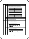
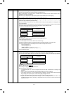
03 Original sensor light reception level and original judgement level display
Used to display the original sensor light reception level and the original judgement level on the copy quantity
display.
Display is selected by the magnification ration selection key.
Since there are two or more display items, the third digit is used to make distinction between the light reception
level and the original judgment level, and the lower two digits are used to display the data. The currently set
original sensor is displayed by the LED on the original size display section. The relationship between the sensor
name and the original size LED is the same as SIM 41-1.
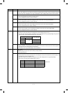
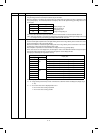
Copy quantity display
Original size
display
Display data
3rd digit 2nd, 1st digits
A Current light
reception level
A5/INV PD0 current light reception level
B5 PD1 current light reception level
A4/LT PD2 current light reception level
B5R PD3 current light reception level
A4R/LTR PD4 current light reception level
B4/LG PD5 current light reception level
A3/WLT PD6 current light reception level
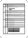
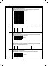
b Original
judgement level
A5/INV PD0 original judgement level
B5 PD1 original judgement level
A4/LT PD2 original judgement level
B5R PD3 original judgement level
A4R/LTR PD4 original judgement level
B4/LG PD5 original judgement level
A3/WLT PD6 original judgement level
OCSW Manual feed tray selection LED
The data displayed by the lower two digits are A/D input values of the original sensor, and is expressed in
hexadecimal. (Display range: 0 ∼ FFh)
The light reception level display is changed only when the original cover is open.
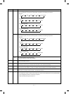
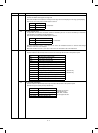
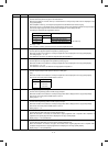
PD1 PD2 PD3 PD4 PD5 PD6
Document lead eddge
8 – 12