


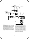
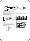
[When the heat roller surface temperature is lower than the set
temperature]
a. Since the thermistor pin voltage is higher then the set level, the
output signal HL from the CPU is driven to LOW.
b. This HL signal is passed through TR Q3 to the solid state relay
(SSR).
When, therefore, the HL signal is LOW, the internal triac turns on.
c. When the internal triac turns on, a pulse is applied to the gate of
external triac to flow a current from the power through the heater
lamp to the triac, lighting the heater lamp.
[When the heat roller surface temperature is higher than the set
level]
a. Since the thermistor pin voltage is lower than the set level, the
output signal HL from the CPU is driven to HIGH.
b. HL is driven to LOW, SSR turns off, the external triac turns off,
and the heater lamp turns off.
[Q3]
Prevents the hater lamp from being lighted always by the trouble in
the heater lamp drive signal harness wiring.
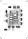
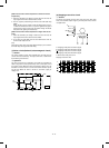
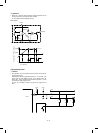
(7) Driver circuit (Solenoid, electromagnetic clutch)
1 General
The control signals of each load outputted from the CPU and I/O
cannot drive the load directly. The output, therefore, is delivered to
the load through the driver IC.
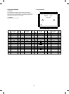
2 Operation
The drive circuit forms a Darlington circuit with two transistors to
obtain a large drive current (load current) from a small input current
(I/O output current). When the driver input voltage is HIGh (+5V), the
transistor is turned on to flow a current in the arrow direction, operat-
ing the load. When the driver is turned on, the driver output pin
voltage is 0V.
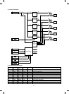
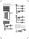
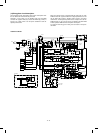
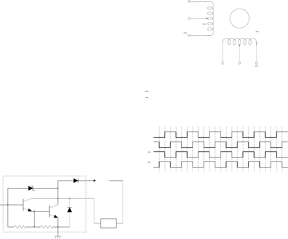
(8) Stepping motor drive circuit
1 General
The driver circuit drives the lens drive motor, the mirror base drive
motor, the automatic duplex copy tray, the side plate motor, and the
rear plate motor.
A: Stepping motor phase A coil drive signal
B: Stepping motor phase B coil drive signal
A: Stepping motor phase A coil drive signal
B: Stepping motor phase B coil drive signal
* Mirror base motor power is Vh.
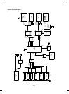
Stepping motor time chart
LOAD
+24V
I/O
output
BB
+24V
Phase B Phase B
A
A
+24V
Phase A
Phase A
A
A
B
B
12 – 13