


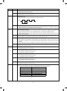
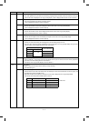
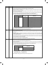
Main code Sub code Content
42 (Note) Developer counter clear
Used to clear the currently installed developing unit counter and to display the developer counter value on the
copy quantity display.
(“000” is displayed because the counter is cleared.)
(Note) The counter is cleared by entering the sub code “01.”
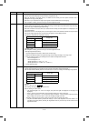
43 01 Fusing temperature setting
Used to set the fusing control temperature.
When this simulation is executed, the currently set fusing temperature is displayed on the copy quantity display.
The set value is changed by pressing the magnification ratio display key.
Select the fusing temperature and press the PRINT button to store it.
The setting range is 160 ∼ 205°C (in the increment of 5°C).
Only in the SF-2120, pressing the duplex key lights up the single → duplex (even number of originals) lamp and
the fusing temperature for duplex copy can be set. The setting procedure is the same as the normal one.
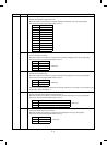
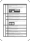
44 01 Process control operation setting
Used to set valid/invalid of the grid voltage correction, optical dirt correction, and drum membrane decrease
correction.
When this simulation is executed, the currently set value is displayed on the copy quantity display.
To make each correction mode valid, enter the sum of the codes of the correction modes, and press the PRINT
button to store it.
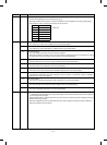
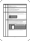
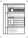
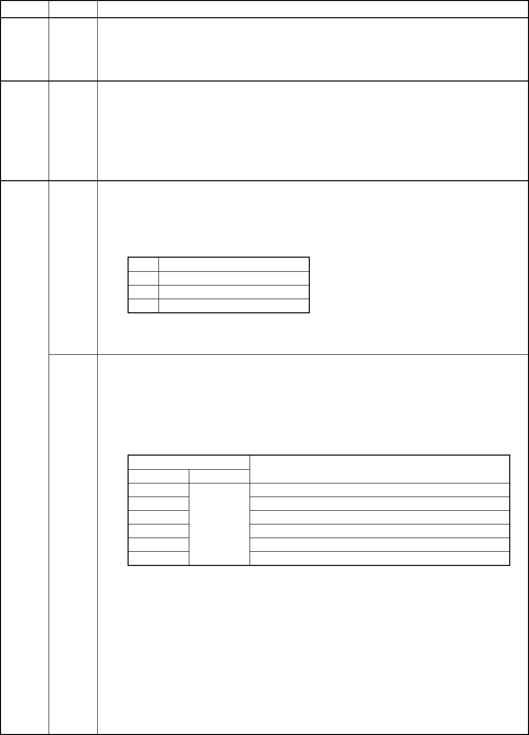
Code Correction mode
+1 Grid voltage correction
+2 Optical dirt correction
+4 Drum membrane decrease correction
The initial value is “7.” (All corrections are valid.)
The grid voltage correction is always valid regardless of set value. (Even if it is set to “0,” the grid voltage
correction is not canceled.)
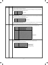
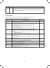
05 Grid voltage correction operation test
Used to perform the grid voltage correction and to display the measure data on the copy quantity display.
When this simulation is executed, the grid voltage correction is automatically performed. The image density
sensor is read when -30V, 0V, and +30V are applied to the latest patch forming grid voltage.
After completion of the operation, the measure data are displayed on the copy quantity display.
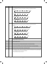
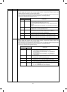
Since there are two or more display items, the third digit is used to make distinction between the light reception
level and the original judgment level, and the lower two digits are used to display the data.
The display is selected by the magnification ratio key.
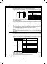
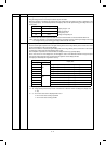
Copy quantity display
Display data (Image density sensor A/D input value)
3rd digit 2nd, 1st digits
A Measured
data
Drum surface data (patch forming grid voltage) –30V is applied.
b Drum surface data (patch forming grid voltage) is applied.
C Drum surface data (patch forming grid voltage) is applied.
d Patch data (patch forming grid voltage) -30V is applied.
E Patch data (patch forming grid voltage) is applied.
F Patch data (patch forming grid voltage) +30V is applied.
The data displayed by the lower two digits are A/D input values of the original sensor, and is expressed in
decimal. (Display range: 0 ∼ 99)
The patch forming grid voltage after execution of this simulation can be checked with SIM 44-9.
8 – 13