


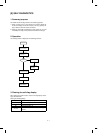

Main code Sub code Content
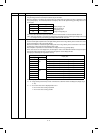
48 02 Paper transport direction magnification ratio adjustment
Used to set the horizontal (paper transport direction) magnification ratio.
When this simulation is executed, warm-up is started and the currently set mirror speed correction value is
displayed on the copy quantity display.
When warm-up is completed, the ready lamp is lighted. Press the PRINT button to start copying.
After completion of setting, press the CA key to cancel the adjustment mode.
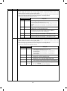
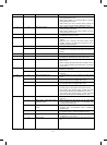
50 01 Lead edge image position adjustment
Used to set the lead edge image position (RRC ON timing), the lead edge void position (blank lamp ON timing),
and the rear edge void position (grid output timing).
When this simulation is executed, warm-up is started and the currently set resist adjustment A is displayed on the
copy quantity display.
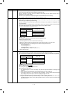
Since there are two or more display items, the third digit is used to make distinction between the light reception
level and the original judgment level, and the lower two digits are used to display the data.
The display is selected by the magnification ratio key.
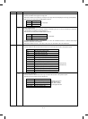
Copy quantity display
Display data
3rd digit 2nd, 1st digits
A1 ∼ 99 Resist adjustment A
b Resist adjustment B
C Lead edge void adjustment
d Rear edge void adjustment
Set range: 1 ∼ 99
After completion of setting, press the CA key to cancel the adjustment mode.
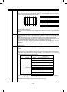
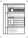
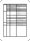
(Lead edge adjustment procedure)
1 Set resist adjustment A and B to 0. Make 100% and 200% copy.
2 Measure the distance between the paper lead edge and the image lead edge in each copy mode.
3 Enter the measured value in the following formula to obtain resist adjustment A and B.
200% lead edge shift : L1
100% lead edge shift : L2
(Resist adjustment A) = 6.151 × (L1 – L2)
(Resist adjustment B) = (15.385 × L2) – (7.692 × L1)
4 Set the obtained values.
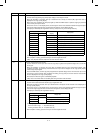
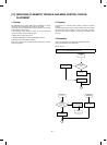
02 Lead edge image position adjustment (measurement value substitution formula)
Used to set the lead edge image position and the lead edge void position similarly with SIM 50-1.
This simulation allows to directly enter the measured values L1 and L2 for setting of the lead edge image position.
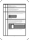
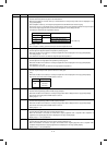
Copy quantity display
Display data
3rd digit 2nd, 1st digit
A1 ∼ 99 L1
bL2
C Lead edge void adjustment
d Rear edge void adjustment
(Example)
When L1 = 24.5mm, enter 2 4 5 .
After entering, the copy quantity display shows “A45.”
Note for entering L1 and L2 values
• The significant digits of L1 and L2 are 3 digits. (Only lower two digits are displayed. The top digit is not
displayed.)
• Enter L1 and L2 to one decimal place. (If the first decimal place is 0, enter 0 at the end.)
• If four digits is entered for L1 or L2, the last three digits are effective. If only two digits is entered, the lowest
digit (1st digit) of the previous input is used as the top digit (3rd digit) of this time.
(Example) If the previous input is 245, and the current input is 24, the stored value is 524.
• Only when the PRINT button is pressed after setting L1 and L2, resist adjustment A and B in SIM 50-1 are
calculated and revised (stored). Pressing the magnification ratio key or the CA key cannot revise the resist
adjustment A and B.
8 – 18