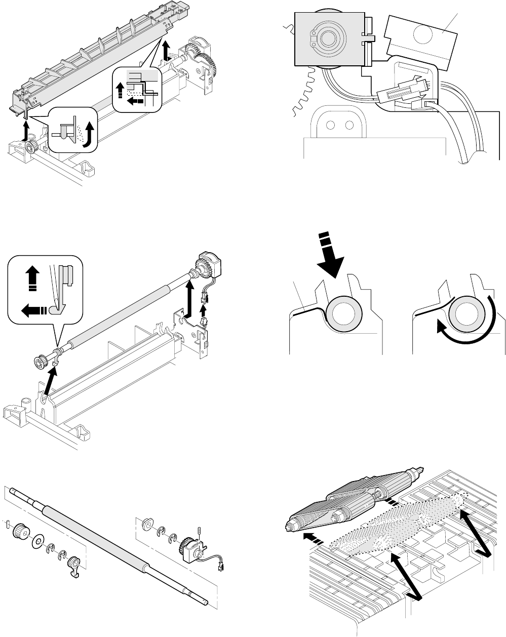
3 Remove the hook of the front frame side bearing, and lift it up to
remove it toward the upper frame side. Remove the rear frame
side connector, and slide and remove the resist roller ass’y toward
the rear frame side.
4 Remove the clutch and the gears as shown below.
(Note for assembly)
1) Attach so that the resist roller clutch projection is on the paper exit
side as shown in the figure below.
2) Arrange the cable and the power grounding wire from the resist
roller clutch as shown in the figure below.
3) Hook the hook section of the TC case as shown below.
4) When attaching the resist roller ass’y to the copier, attach over the
upper side of the PS roller lower mylar, then rotate the roller to set
the mylar to the normal position. (If the mylar is deformed, it may
cause paper jam. Replace it if deformed.)
2-2. Transport belt
1 Remove the fusing unit.
2 Remove the TC case.
3 Disengage the transport belt drive shaft holder on the TC case
side, then disengage the drive shaft on the paper exit side and
remove the belt.
(Note for assembly)
1
There is a mark ( î ) on the transport belt. Set so that the tip of
the mark faces toward the paper exit direction.
2 Be careful of the installing direction of the transport belt drive
shaft.
TC/SC case
PS mylar
6 – 4


